
User's Manual
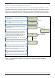
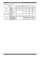
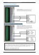
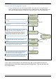
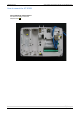
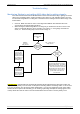
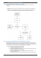
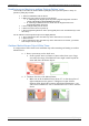
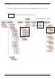
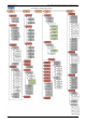
Table Of Contents
- Table of Contents
- Introduction:
- In order for an installation to be UL compliant you must follow the specifications in the table below:
- XT Initial Programming
- XT-IP620 Programming
- Device Installation
- Entering a Badge or Access Code for Arming/Disarming
- Configuration of Special Arming Modes:
- How to Disable/Enable Monitoring
- ETHERNET Parameters:
- How to test to the dispatch center
- How to Disable Monitoring
- How to test RF for deployment of devices
- XT-IP620 Power Chart
- Arming Input Wiring Diagram
- How to test to the dispatch center
- How to mount the XT-IP620
- Troubleshooting
- Monitoring Station is not getting ANY video but is getting signals:
- Monitoring Station is not getting any signals:
- Panel is staying CONNECTED WITH MONITOR STATION
- Unable to record device or getting ‘Pairing Failure’ error
- Outdoor MotionViewer Trips All the Time:
- XT-IP620 -SERIES ‘AFTER INITIAL PROGRAMMING’ FLOW CHART
- 1. LSH20 Control Panel Batteries:
- 2. LS14500 Peripheral Batteries: Excludes SE601 and SE651
- 3. Lithium Battery Storage:
- 4. Finding Manufacture Week and Year:
- 5. Event Log Ethernet Codes
- 6. Additional System Codes
- 7. Replacing Device and Control Panel batteries
- 8. Checking control panel firmware version

2012/1/9 Ed 1.1 Setup and Programming manual for XT-IP620 series
21 | Page
How to test RF for deployment of devices
Running the RF test during the mounting of devices is key to a successful Videofied installation. This test
will ensure that all devices have adequate communication with the control panel. All Videofied devices are
bi-directional which allows the system to ping the device and expect a response. The number of successful
responses out of 9 will be displayed on the keypad for the device you are running the test for. This is also a
relative range that will change in real time as you walk further away from the control panel and back closer.
10/12/27 10:53
DISARMED LVL:3
DEVICE LOCATING
RF TEST
0/9
When in Access Level 3 or higher press the
arrow to move
to MAINTENANCE
Press the arrow to move to DEVICE LOCATING
(DEVICE NAME)
Press and hold ESC/NO for 5 seconds to return to the main
menu.
This test will run as long as you need it to. Pressing the
YES/OK, ESC/NO, or CLR buttons will end the test. This
test will show the results on the display of the keypad
relative to the number of successful pings to the panel. It is
required to run the test for at least 30 seconds at the
mounting location for accurate results and to have a 9/9 for
reliable transmission of alarms and video. Press YES/OK
when you are finished with the test.
YES/OK
YES/OK
MAINTENANCE
Press YES/OK on DEVICE LOCATING to get to the list of
devices. Use the arrow keys to find the device you would like
to run the test for.
(DEVICE NAME)
YES/OK
YES/OK
Once all devices are checking in at 9/9, you are ready to test
the full system to your central station. After arming and
tripping each device call the central station and verify alarm
and video of each device with dispatch.
Now you are ready to show the customer how to use the
system.
NOTE: To insure proper operation of the system you must get 9/9 with each device
before mounting.