
User's Manual
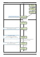
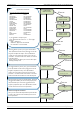
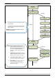
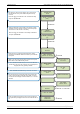
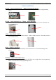
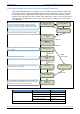
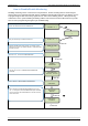
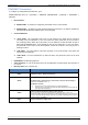
Table Of Contents
- Table of Contents
- Introduction:
- In order for an installation to be UL compliant you must follow the specifications in the table below:
- XT Initial Programming
- XT-IP620 Programming
- Device Installation
- Entering a Badge or Access Code for Arming/Disarming
- Configuration of Special Arming Modes:
- How to Disable/Enable Monitoring
- ETHERNET Parameters:
- How to test to the dispatch center
- How to Disable Monitoring
- How to test RF for deployment of devices
- XT-IP620 Power Chart
- Arming Input Wiring Diagram
- How to test to the dispatch center
- How to mount the XT-IP620
- Troubleshooting
- Monitoring Station is not getting ANY video but is getting signals:
- Monitoring Station is not getting any signals:
- Panel is staying CONNECTED WITH MONITOR STATION
- Unable to record device or getting ‘Pairing Failure’ error
- Outdoor MotionViewer Trips All the Time:
- XT-IP620 -SERIES ‘AFTER INITIAL PROGRAMMING’ FLOW CHART
- 1. LSH20 Control Panel Batteries:
- 2. LS14500 Peripheral Batteries: Excludes SE601 and SE651
- 3. Lithium Battery Storage:
- 4. Finding Manufacture Week and Year:
- 5. Event Log Ethernet Codes
- 6. Additional System Codes
- 7. Replacing Device and Control Panel batteries
- 8. Checking control panel firmware version

2012/1/9 Ed 1.1 Setup and Programming manual for XT-IP620 series
15 | Page
RECORDING
DEVICES
PRESS PROGRAM
BUTTON OF DEVICE
ENTERING A NEW
DEVICE?
CLOSE THE PANEL
OPERATION
COMPLETED?
YES/OK
YES/OK
Each device has a unique programming button. Please
reference the Installation Sheet for the device you would like
to program.
Before completing programming make sure that all tampers
are depressed by verifying that each devices indicator LED is
off.
(Device Type) #
Recorded
RADIO RANGE
TEST?
RF TEST
x/9
RADIO RANGE
TEST?
AREA ALLOCATION:
NAME LOCATION:
FUNCTIONAL
DEVICE TEST?
YES/OK or ESC/NO
Press YES/OK on Radio Range Test? You must allow the
Radio Range test to run for at least 30 seconds (9/9) before
stopping the test by pressing YES/OK.
Press ESC/NO if first Radio Range Test was successful.
Use the arrow keys to select the proper area. Devices that
need an entry/exit delay should be set to AREA 1. Devices
that must be instant trigger should be AREA 2, 3, or 4. Press
YES/OK.
*Note: If you are having issues pairing a device to the panel,
please refer to the troubleshooting section.
TRANSMISSION
DELAY
Value: (0-600)
(000):
ARMING
CONFIRMATION
Value: (0-240)
(0):
YES/OK
By entering a value using the keypad, up to 600 seconds,
the transmission of any event will be delayed that many
seconds.
Enter the value you would like for the Transmission Delay
and press
YES/OK
Arming Confirmation is the number of seconds the system
will wait to arm after voltage is latched on the arming input.
This feature can be used as an exit delay.
Enter the value you would like for the Arming Confirmation
and press
YES/OK
YES/OK