
User's Manual
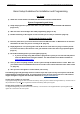
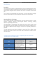
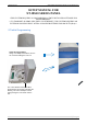
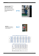
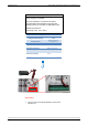
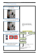
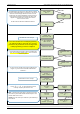
Table Of Contents
- Table of Contents
- Introduction:
- In order for an installation to be UL compliant you must follow the specifications in the table below:
- XT Initial Programming
- XT-IP620 Programming
- Device Installation
- Entering a Badge or Access Code for Arming/Disarming
- Configuration of Special Arming Modes:
- How to Disable/Enable Monitoring
- ETHERNET Parameters:
- How to test to the dispatch center
- How to Disable Monitoring
- How to test RF for deployment of devices
- XT-IP620 Power Chart
- Arming Input Wiring Diagram
- How to test to the dispatch center
- How to mount the XT-IP620
- Troubleshooting
- Monitoring Station is not getting ANY video but is getting signals:
- Monitoring Station is not getting any signals:
- Panel is staying CONNECTED WITH MONITOR STATION
- Unable to record device or getting ‘Pairing Failure’ error
- Outdoor MotionViewer Trips All the Time:
- XT-IP620 -SERIES ‘AFTER INITIAL PROGRAMMING’ FLOW CHART
- 1. LSH20 Control Panel Batteries:
- 2. LS14500 Peripheral Batteries: Excludes SE601 and SE651
- 3. Lithium Battery Storage:
- 4. Finding Manufacture Week and Year:
- 5. Event Log Ethernet Codes
- 6. Additional System Codes
- 7. Replacing Device and Control Panel batteries
- 8. Checking control panel firmware version

2012/1/9 Ed 1.1 Setup and Programming manual for XT-IP620 series
10 | Page
ENTER THE
INSTALLER CODE
4 TO 6 DIGITS
THEN YES/OK
INSTALLER CODE:
INSTALLER CODE:
xxxx
YES/OK
CONFIRM CODE
RE-ENTER CODE
CONFIRM CODE
xxxx
CODE NAME:
ACCESS 1
ENTRY COMPLETE
RADIO RANGE
TEST ?
RF TEST
x/9
YES/OK
ESC/NO
SETTING
DATE AND TIME
SETTING:
AUTO
SETTING:
MANUAL
DATE (Year) :
13/
DATE (Month) :
13/11/
YES/OK
YES/OK
Wait while the screen changes
Use the Alphanumeric Keypad to enter the Installer Code
*This code is important to keep track of. There is no back
door to the system
You may name the installer code using the Alphanumeric
Keypad. If you leave the name blank it will default to
‘ACCESS 1’
Use the
or
to choose between Auto and
manually configuring the Date and Time
Auto: You will use the arrow keys to choose the UTC time
zone that the panel will be installed at followed by the exact
location within the time zone.
Manual: Use the arrow keys to define the year/ Month/ Day/
Hour/ Minute.
RADIO RANGE
TEST ?
YES/OK
The Radio Range test must be run during device recording
to ensure proper pairing with the control panel. This test the
number of successful pings between the device and the
control panel. The keypad will display a real time RF level
for the device that is being tested. This test will run until
stopped and should be run for at least 30 seconds to
receive accurate results.
The RF level must be 9/9 for reliable transmission.
Wait while the screen changes
TIMEZONE:
UTC-05
From here until the end of initial programming
you will not be able to step back to a previous
parameter. All parameters can be changed after
initial programming has been completed.
YES/OK
UTC-06:
CENTRAL (US/CAN)