Document #2029-XTIPIN COMPLETE SETUP AND PROGRAMMING MANUAL FOR XT-IP620 *A Videofied CMA/XMA/WMB Alphanumeric Keypad or Frontel TMT2 is required for programming and maintenance* CMA XMA WMB
012/1/9 Ed 1.
2012/1/9 Ed 1.1 Setup and Programming manual for XT-IP620 series Regulatory Information for USA and Canada FCC Part 15.21 Changes or modifications made to this equipment not expressly approved by RSI Video Technologies may void the FCC authorization to operate this equipment. FCC Part 15.105 Class B This equipment has been tested and found to comply with the limits for a Class B digital device, pursuant to Part 15 of the FCC Rules.
2012/1/9 Ed 1.1 Setup and Programming manual for XT-IP620 series Basic Setup Guidelines for Installation and Programming Pre-Setup 1) Obtain the account number and IP/Domain information from the Central Station. System Programming and Setup 1) Setup and program the system in the office or in your vehicle. DO NOT MOUNT THE DEVICES. (Pages 6-15) 2) Add user codes and or badges after initial programming. (Pages 17-18) 3) Disable monitoring so that signals are not sent until you are ready to send them.
2012/1/9 Ed 1.1 Setup and Programming manual for XT-IP620 series Introduction: Description: The XT-IP620 control panel is a Videofied wireless, battery operated hybrid alarm system. It is designed for residential, small business and commercial security applications. The XTIP620 provides integrated Video Verification and features an Ethernet communication path. The XT-IP620 has programmable inputs and outputs.
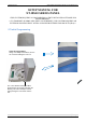
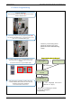
2012/1/9 Ed 1.1 Setup and Programming manual for XT-IP620 series SETUP MANUAL FOR XT-IP620 SERIES PANEL *THIS SYSTEM REQUIRES A CMA/WMB/XMA or TMT2 INSTALLER SOFTWARE FOR PROGRAMMING* **TO TRANSMIT ALARMS AND VIDEO VIA ETHERNET, THE SYSTEM REQUIRES AN EXTERNAL POWER SUPPLY WITH 4 ALKALINE BATTERIES FOR BACK-UP (PP4)** XT Initial Programming Open the Control Panel Using a #1 Phillips screwdriver, remove the 2 screws holding the cover on.
2012/1/9 Ed 1.1 Setup and Programming manual for XT-IP620 series Connect the RJ45 (Ethernet cable) to the panel Plug the RJ45 cable into the Ethernet jack on the control panel. The cable can be routed back through the wire channel to make sure it does not get pinched. Important: When the panel attempts a transmission via Ethernet a red LED will flash.
2012/1/9 Ed 1.
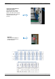
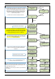
2012/1/9 Ed 1.1 Setup and Programming manual for XT-IP620 series XT-IP620 Programming Reset the XTIP Panel: Press and hold programming button () for 10sec until the Indicator LED blinks twice Press and instantly release the programming button (). The indicator LED will blink once. The panel is now in ‘Learn Mode’ for the CMA/XMA/WMB keypad. *NOTE: If you are having issues pairing the keypad to the panel, please refer to the troubleshooting section.
2012/1/9 Ed 1.1 Setup and Programming manual for XT-IP620 series The Radio Range test must be run during device recording to ensure proper pairing with the control panel. This test the number of successful pings between the device and the control panel. The keypad will display a real time RF level for the device that is being tested. This test will run until stopped and should be run for at least 30 seconds to receive accurate results.
2012/1/9 Ed 1.1 Setup and Programming manual for XT-IP620 series DATE (Day) : 13/11/05 YES/OK TIME (HOUR) : 10:00 YES/OK DATE (Minutes) : 10:53 YES/OK YOU MUST ALWAYS CHOOSE ‘YES/OK’ CONNECTED TO MONITOR.STATION? YES/OK ACCOUNT NUMBER? Use the Alphanumeric Keypad to enter in a 4-8 digit account number provided by the Central Station ACCOUNT NUMBER: 99865123 YES/OK Other periods are available: 24 hours, 12 hours,1 hour, 7 days No Test Use arrows for the selection and press confirm.
2012/1/9 Ed 1.1 Setup and Programming manual for XT-IP620 series CODE/STATE modification These are the default transmitted events: Device Event Alert Event Panel Reset Not Transmitted Panel Batteries Event/Restore AC Power Event/Restore Phoneline Fault Not Transmitted Tamper Event/Restore Device Batt.
2012/1/9 Ed 1.1 Setup and Programming manual for XT-IP620 series ETHERNET PARAMETERS DHCP: ENABLE OR DISABLE DISABLE PANEL IP • These parameters are not necessary if you choose DHCP ENABLE • These parameters are the local network parameters. It’s necessary to configure all these parameters if DHCP is disabled. IP MASK ENABLE GATEWAY IMPORTANT: Verify that the IP address selected is available on the Network.
2012/1/9 Ed 1.1 Setup and Programming manual for XT-IP620 series Enter the name of the logical area 1 + YES/OK. Repeat this step for areas 2, 3, 4. Refer to page 4 for more information. AREAS CONFIGURATION Press ESC/NO if you want to let default value. Note: Areas are designed to define logical separation AREA NAME 1: ARMING OPTION: Your choice will depend on how you are arming the system.
2012/1/9 Ed 1.1 Setup and Programming manual for XT-IP620 series By entering a value using the keypad, up to 600 seconds, the transmission of any event will be delayed that many seconds. TRANSMISSION DELAY Enter the value you would like for the Transmission Delay Value: (0-600) (000): and press YES/OK YES/OK Arming Confirmation is the number of seconds the system will wait to arm after voltage is latched on the arming input. This feature can be used as an exit delay.
2012/1/9 Ed 1.1 Setup and Programming manual for XT-IP620 series Device Installation DCV651 – Outdoor MotionViewer / BR651 Outdoor Badge Reader Place batteries in Device. Wait for LED to turn on. Press and release the programming button. DCV601 – Indoor MotionViewer / ITR601 – Indoor Blind PIR Place batteries in device. Wait for LED to turn on behind PIR lens. Press and release the programming button. DCV601 ITR601 CT601 – Door/Window Contact Place battery into the door/window contact.
2012/1/9 Ed 1.1 Setup and Programming manual for XT-IP620 series Entering a Badge or Access Code for Arming/Disarming After Initial programming has been completed, you are not able to arm and disarm the system until you enter a user code or badge (the installer code cannot arm and disarm the system).
2012/1/9 Ed 1.1 Setup and Programming manual for XT-IP620 series Access level Definition & rights LVL1 Stand by level LVL2 Restricted USER level where it is only possible to arm/disarm the system. LVL3 USER level where it is possible to arm/disarm the system, check the event log, test the devices. Modifications of the setting are not possible at this level. User LVL3 can create LVL3 or LVL2 access codes. INSTALLER level where it is possible to modify the setup of the panel.
2012/1/9 Ed 1.1 Setup and Programming manual for XT-IP620 series How to Disable/Enable Monitoring Disabling monitoring can be a useful tool in many situations. Before mounting devices and moving the panel to find a good communication with devices, disabling monitoring will ensure that you will have access to programming and that unnecessary signals are not sent to the monitoring station.
12/1/9 Ed 1.1 Setup and Programming manual for XT-IP620 series ETHERNET Parameters: nging Siren Options To configure or modify Ethernet Parameters, go to: CONFIGURATION (level 4) + [YES/OK] >> GENERAL PARAMETERS + [YES/OK] >> ETHERNET + After initial programming has been completed any sounder on the system will be enabled by default, [YES/OK] this includes the sounder on the Keypad and Badge Reader. While there is no way to disable the of the exit delay you are able to disable the intrusion sound.
2012/1/9 Ed 1.1 Setup and Programming manual for XT-IP620 series How to test RF for deployment of devices Running the RF test during the mounting of devices is key to a successful Videofied installation. This test will ensure that all devices have adequate communication with the control panel. All Videofied devices are bi-directional which allows the system to ping the device and expect a response.
2012/1/9 Ed 1.
2012/1/9 Ed 1.1 Setup and Programming manual for XT-IP620 series Arming Input Wiring Diagram When in the ‘Arm From Host’ mode the Videofied system will only arm and disarm when 9-12v is supplied and sustained. When both arming inputs are supplied voltage at the same time the Videofied Keypad display will show ‘SYSTEM ARMED.
2012/1/9 Ed 1.1 Setup and Programming manual for XT-IP620 series How to test to the dispatch center Testing to the dispatch is done twice during installation. Once while you are programming the system and then again once the installation has been completely finished. Although both will use the same steps the initial test will be just confirmation using one device to verify the programming. 10/12/27 10:53 DISARMED LVL:1 Enter a User code and press YES/OK or present a badge to the reader.
2012/1/9 Ed 1.1 Setup and Programming manual for XT-IP620 series How to mount the XT-IP620 How to Mount the Control Panel? Fix the back casing on the wall with 3 screws () .
2012/1/9 Ed 1.1 Setup and Programming manual for XT-IP620 series Troubleshooting Monitoring Station is not getting ANY video but is getting signals: Good communication between the MotionViewers and the Control Panel is key to getting successful video to the monitoring station. During mounting of any device on your Videofied system you must run the Radio Range/Device Locating test to ensure that the mounting location is with-in range of the Control Panel.
2012/1/9 Ed 1.1 Setup and Programming manual for XT-IP620 series Monitoring Station is not getting any signals: Communication between the Control Panel and the Monitoring Station is over an Ethernet Connection. Go into Maintenance and run the ETH STATUS to see if you receive back an IP Address or error. If you receive an IP Address back you will want to contact and consult the network admin to make sure the outbound port is not being blocked (Port 1 programmed in the panel).
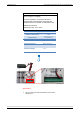
2012/1/9 Ed 1.1 Setup and Programming manual for XT-IP620 series Unable to record device or getting ‘Pairing Failure’ error This usually occurs when the device still has a pairing key from a previous system or setup. To perform a pairing key override: o o o o o 1. Remove all batteries from the device. 2. Make sure your system is ready to record devices: o A. If learning in the keypad, press the panel’s programming button. DO NOT HOLD THE PANEL’S PROGRAMMING BUTTON o B.
2012/1/9 Ed 1.
2012/1/9 Ed 1.
2012/1/9 Ed 1.1 Setup and Programming manual for XT-IP620 series Addendum 1. LSH20 Control Panel Batteries: 2. LS14500 Peripheral Batteries: Excludes SE601 and SE651 3.
2012/1/9 Ed 1.1 Setup and Programming manual for XT-IP620 series 4. Finding Manufacture Week and Year: The Manufacture week and year can be found in the serial number of the device/control panel. The second sets of 4 numbers in the serial number are WWYY. ####0411######## = Which shows that this device was manufactured in the 4th week of 2011. 5.
2012/1/9 Ed 1.1 Setup and Programming manual for XT-IP620 series 7. Replacing Device and Control Panel batteries When replacing batteries in the Videofied control panel or devices the battery replacement mode must be used. This will ensure that the low battery algorithm on the panel/device is properly reset and also helps keep the devices synced with the control panel.