Document #2002-XTIPIN COMPLETE SETUP AND PROGRAMMING MANUAL FOR XT-IP 630 PANELS A Videofied CMA/XMB/XMA/WMB Alphanumeric Keypad or Frontel TMT2 is required for programming and maintenance WMB CMA XMB/XMA 1375 Willow Lake Blvd.
013/01/18 Ed 1 Setup and Programming manual for XTIP series Table of Contents Page FCC 3 Installation Guidelines 4 Introduction 5 Initial Programming 6-16 Device Installation 17 Disabling Monitoring 18 Entering Badges and Access Codes 19-20 Choosing Siren Options 20 Ethernet Parameters and Testing 21 Testing GPRS / 3G Level and Error Codes List 22 Testing Device RF Level 23 XTIP Power Chart 24 Arming Input Wiring Diagram 25 Testing to Central Station 26 Mounting XT/XTX 27
2013/01/18 Ed 1 Setup and Programming manual for XTIP series Regulatory Information for USA and Canada FCC Part 15.21 Changes or modifications made to this equipment not expressly approved by RSI Video Technologies may void the FCC authorization to operate this equipment. FCC Part 15.105 Class B This equipment has been tested and found to comply with the limits for a Class B digital device, pursuant to Part 15 of the FCC Rules.
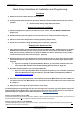
2013/01/18 Ed 1 Setup and Programming manual for XTIP series Basic Setup Guidelines for Installation and Programming Pre-Setup 1) Obtain the account number from the Central Station. 2) If using Cellular communication for primary or backup, activate the SIM card through your cellular provider a. *Do these steps at least 1 day before the install. System Programming and Setup 1) Setup and program the system in the office or in your vehicle. DO NOT MOUNT THE DEVICES.
2013/01/18 Ed 1 Setup and Programming manual for XTIP series Introduction: Description: The XTIP control panel is a Videofied wireless, battery operated hybrid alarm system. It is designed for residential, small business and commercial security applications. The XTIP provides integrated Video Verification and features dual communication paths: Ethernet and 2G3G (3G or less). The XTIP has programmable inputs and outputs.
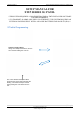
2013/01/18 Ed 1 Setup and Programming manual for XTIP series SETUP MANUAL FOR XTIP SERIES 3G PANEL *THIS SYSTEM REQUIRES A CMA/XMB/XMA/WMB or TMT2 INSTALLER SOFTWARE FOR PROGRAMMING* **TO TRANSMIT ALARMS AND VIDEO VIA ETHERNET, THE SYSTEM REQUIRES AN EXTERNAL POWER SUPPLY WITH 4 ALKALINE BATTERIES FOR BACK-UP (PP4)** XT Initial Programming Open the Control Panel Using a #1 Phillips screwdriver, remove the 2 screws holding the cover on.
2013/01/18 Ed 1 Setup and Programming manual for XTIP series *The SIM card must NOT be inserted or removed while the panel is powered* Install the SIM card Slide SIM card into the slot. Make sure it is aligned correctly. The SIM card is not required if you plan to use Ethernet only. Connect the RJ45 (Ethernet cable) to the panel Plug the RJ45 cable into the Ethernet jack on the control panel. The cable can be routed back through the wire channel to make sure it does not get pinched.
2013/01/18 Ed 1 Setup and Programming manual for XTIP series Powering the Panel **THE CONTROL PANEL MUST BE CONNECTED TO AN EXTERAL POWER SUPPLY WHEN ETHERNET FEATURE IS ACTIVE** Option 1: PP1 4 x LSH20 SAFT Lithium D-Cell Used for Standalone or Xtender mode without Programmable Inputs, Programmable Outputs, Ethernet, or SMS LSH20 Specifications: Operating Temp: -76°F to +230°F Storage Temp: Dry, Ventilated, 86°F Max LSH20 Technical Specifications Nominal Voltage 3.6 V Open Circuit Voltage 3.
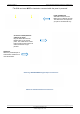
2013/01/18 Ed 1 Setup and Programming manual for XTIP series XTIP Programming Reset the XTIP Panel: Press and hold programming button () for 10sec until the Indicator LED blinks twice Press and instantly release the programming button (). The indicator LED will blink once. The panel is now in ‘Learn Mode’ for the CMA601/XMB-XMA-WMB611 keypad. *Note: If you are having issues pairing the keypad to the panel, please refer to the troubleshooting section.
2013/01/18 Ed 1 Setup and Programming manual for XTIP series The Radio Range test must be run during device recording to ensure proper pairing with the control panel. This tests the number of successful pings between the device and the control panel. The keypad will display a real time RF level for the device that is being tested. This test will run until stopped and should be run for at least 30 seconds to receive accurate results.
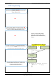
2013/01/18 Ed 1 Setup and Programming manual for XTIP series YES/OK Use the or DATE (Day) : 09/06/01 to set the Day DATE (Day) : 09/06/03 YES/OK Use the or to set the Hour – The system uses a 24 hour clock.
2013/01/18 Ed 1 Setup and Programming manual for XTIP series CODE/STATE modification CODE/STATE MODIFICATION? These are the default transmitted events: Device Alarm Alert Alarm Initialization Not Transmitted Panel Batteries Alarm/End AC Power Alarm/End Phoneline Fault Not Transmitted Tamper Alarm/End Device Batt.
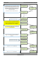
2013/01/18 Ed 1 Setup and Programming manual for XTIP series Press right arrow to select the transmission mode for alarms and videos and YES/OK to confirm. 1. Ethernet transmission with 2G3G back-up 2. Ethernet transmission only 3. 2G3G transmission only STRATEGY ETH+2G3G YES /OK STRATEGY: ETH YES/OK Warning: the transmission mode “Ethernet only” is not recommended.
2013/01/18 Ed 1 Setup and Programming manual for XTIP series ETHERNET PARAMETERS DHCP: ENABLE OR DISABLE OU INACTIF DISABLE PANEL IP • These parameters are not necessary if you choose DHCP ENABLE • These parameters are the local network parameters. It’s necessary to configure all these parameters if DHCP is disabled. IP MASK ENABLE GATEWAY IMPORTANT: Verify that the IP address selected is available on the Network.
2013/01/18 Ed 1 Setup and Programming manual for XTIP series Enter the name of the logical area 1 + YES/OK. Repeat this step for areas 2, 3, 4. Refer to page 4 for more information. AREAS CONFIGURATION Press ESC/NO if you want to let default value. Note: Areas are designed to define logical separation between groups of devices. AREA NAME 1: ARMING OPTION: Your choice will depend on how you are arming the system.
2013/01/18 Ed 1 Setup and Programming manual for XTIP series By entering a value using the keypad, up to 600 seconds, the transmission of any event will be delayed that many seconds. Enter the value you would like for the Transmission Delay and press YES/OK TRANSMISSION DELAY Value: (0-600) (000): YES/OK Arming Confirmation is the number of seconds the system will wait to arm after voltage is latched on the arming input. This feature can be used as an exit delay.
2013/01/18 Ed 1 Setup and Programming manual for XTIP series Device Installation DCV651 – Outdoor MotionViewer / BR651 Outdoor Badge Reader Place batteries in Device. Wait for LED to turn on. Press and release the programming button. DCV601 – Indoor MotionViewer / ITR601 – Indoor Blind PIR Place batteries in device. Wait for LED to turn on behind PIR lens. Press and release the programming button. DCV601 ITR601 CT601 – Door/Window Contact Place battery into the door/window contact.
2013/01/18 Ed 1 Setup and Programming manual for XTIP series How to Disable/Enable Monitoring Disabling monitoring can be a useful tool in many situations. Before mounting devices and moving the panel to find a good GPRS / 3G level, disabling monitoring will ensure that you will have access to programming and that unnecessary signals are not sent to the monitoring station.
2013/01/18 Ed 1 Setup and Programming manual for XTIP series Entering a Badge or Access Code for Arming/Disarming After Initial programming has been completed, you are not able to arm and disarm the system until you enter a user code or badge (the installer code cannot arm and disarm the system).
13/01/18 Ed 1 Setup and Programming manual for XTIP series Access level Definition & rights LVL1 Stand by level LVL2 Restricted USER level where it is only possible to arm/disarm the system. LVL3 USER level where it is possible to arm/disarm the system, check the event log, test the devices. Modifications of the setting are not possible at this level. User LVL3 can create LVL3 or LVL2 access codes. INSTALLER level where it is possible to modify the setup of the panel.
2013/01/18 Ed 1 Setup and Programming manual for XTIP series ETHERNET Parameters: nging Siren Options To configure or modify Ethernet Parameters, go to: CONFIGURATION (level 4) + [YES/OK] >> GENERAL PARAMETERS + [YES/OK] >> ETHERNET + After initial programming has been completed any sounder on the system will be enabled by default, [YES/OK] this includes the sounder on the Keypad and Badge Reader. While there is no way to disable the of the exit delay you are able to disable the intrusion sound.
2013/01/18 Ed 1 Setup and Programming manual for XTIP series GPRS / 3G for deployment of panel Before the system is mounted you will need to check the GPRS / 3G level to make sure it is adequate. If the level is 3/5 or better you can mount the control panel in that location.
2013/01/18 Ed 1 Setup and Programming manual for XTIP series How to test RF for deployment of devices Running the RF test during the mounting of devices is key to a successful Videofied installation. This test will ensure that all devices have adequate communication with the control panel. All Videofied devices are bi-directional which allows the system to ping the device and expect a response.
2013/01/18 Ed 1 Setup and Programming manual for XTIP series XTIP Power Chart 1375 Willow Lake Blvd.
2013/01/18 Ed 1 Setup and Programming manual for XTIP series Arming Input Wiring Diagram When in the ‘Arm From Host’ mode the Videofied system will only arm and disarm when 9-12v is supplied and sustained. When both arming inputs are supplied voltage at the same time the Videofied Keypad display will show ‘SYSTEM ARMED.
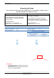
2013/01/18 Ed 1 Setup and Programming manual for XTIP series How to test to the dispatch center Testing to the dispatch is done twice during installation. Once while you are programming the system and then again once the installation has been completely finished. Although both will use the same steps the initial test will be just confirmation using one device to verify the programming. 10/12/27 10:53 DISARMED LVL:1 Enter a User code and press YES/OK or present a badge to the reader.
2013/01/18 Ed 1 Setup and Programming manual for XTIP series How to mount the XTIP How to Mount the Control Panel? Fix the back casing on the wall with 3 screws () . 1375 Willow Lake Blvd.
2013/01/18 Ed 1 Setup and Programming manual for XTIP series General Programmable Input Configuration 1375 Willow Lake Blvd.
2013/01/18 Ed 1 Setup and Programming manual for XTIP series 1375 Willow Lake Blvd.
2013/01/18 Ed 1 Setup and Programming manual for XTIP series 1375 Willow Lake Blvd.
2013/01/18 Ed 1 Setup and Programming manual for XTIP series General Programmable Output Configuration 1375 Willow Lake Blvd.
2013/01/18 Ed 1 Setup and Programming manual for XTIP series 1375 Willow Lake Blvd.
2013/01/18 Ed 1 Setup and Programming manual for XTIP series 1375 Willow Lake Blvd.
2013/01/18 Ed 1 Setup and Programming manual for XTIP series Scheduling Configuration 1375 Willow Lake Blvd.
2013/01/18 Ed 1 Setup and Programming manual for XTIP series 1375 Willow Lake Blvd.
2013/01/18 Ed 1 Setup and Programming manual for XTIP series 1375 Willow Lake Blvd.
2013/01/18 Ed 1 Setup and Programming manual for XTIP series Troubleshooting Monitoring Station is not getting ANY video but is getting signals: Good communication between the MotionViewers and the Control Panel is key to getting successful video to the monitoring station. During mounting of any device on your Videofied system you must run the Radio Range/Device Locating test to ensure that the mounting location is with-in range of the Control Panel.
2013/01/18 Ed 1 Setup and Programming manual for XTIP series Monitoring Station is not getting any signals: Communication between the Control Panel and the Monitoring Station is either over the Ethernet Connection or GPRS / 3G side of the GSM cellular network. Go into Maintenance and run the ETH STATUS to see if you receive back an IP Address or error.
2013/01/18 Ed 1 Setup and Programming manual for XTIP series Unable to record device or getting ‘Pairing Failure’ error This usually occurs when the device still has a pairing key from a previous system or setup. To perform a pairing key override: o o o o o 1. Remove all batteries from the device. 2. Make sure your system is ready to record devices: o A. If learning in the keypad, press the panel’s programming button. DO NOT HOLD THE PANEL’S PROGRAMMING BUTTON o B.
2013/01/18 Ed 1 Setup and Programming manual for XTIP series XTIP -SERIES ‘AFTER INITIAL PROGRAMMING’ FLOW CHART Parameters are only available in Access Level 4 1375 Willow Lake Blvd.
2013/01/18 Ed 1 Setup and Programming manual for XTIP series 1375 Willow Lake Blvd.
2013/01/18 Ed 1 Setup and Programming manual for XTIP series Addendum 1. LSH20 Control Panel Batteries: 2. LS14500 Peripheral Batteries: Excludes SE601 and SE651 3. Lithium Battery Storage: 1375 Willow Lake Blvd.
2013/01/18 Ed 1 Setup and Programming manual for XTIP series 4. Finding Manufacture Week and Year: The Manufacture week and year can be found in the serial number of the device/control panel. The second sets of 4 numbers in the serial number are WWYY. ####0411######## = Which shows that this device was manufactured in the 4th week of 2011. 5.