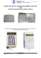
Document #2000-XTIN COMPLETE SETUP AND PROGRAMMING MANUAL FOR XT610/XTX610/XTO610 GPRS PANELS *A Videofied CMA601 / XMB611(June 2011) Alphanumeric Keypad or Frontel TMT2 is required for programming and maintenance* CMA601 XMB611 4455 White Bear Parkway White Bear Lake, MN 55110 877-206-5800
011/11/10 Ed 1.
2011/11/10 Ed 1.5 Setup and Programming manual for XT series GPRS Regulatory Information for USA and Canada FCC Part 15.21 Changes or modifications made to this equipment not expressly approved by RSI Video Technologies may void the FCC authorization to operate this equipment. FCC Part 15.105 Class B This equipment has been tested and found to comply with the limits for a Class B digital device, pursuant to Part 15 of the FCC Rules.
2011/11/10 Ed 1.5 Setup and Programming manual for XT series GPRS Basic Setup Guidelines for Installation and Programming SETUP AND PROGRAM 1) Obtain the account number, IP address, and port number from the Central Station. 2) Activate the SIM card and obtain the APN code, username, and password by calling your cellular provider. *Note: Do step 1 and 2 the day before the install. 3) Setup and program the system in the office or in your vehicle. DO NOT MOUNT THE DEVICES.
2011/11/10 Ed 1.5 Setup and Programming manual for XT series GPRS Introduction: Description: The XT series control panel is a Videofied wireless, battery operated hybrid alarm system. It is designed for residential, small business and commercial security applications. The XT provides integrated Video Verification over GPRS. The XT has programmable inputs and outputs. XT also features mapping where an external input can be used to generate a video clip from a MotionViewer.
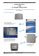
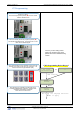
2011/11/10 Ed 1.5 Setup and Programming manual for XT series GPRS SETUP MANUAL FOR XT SERIES GPRS PANEL *THIS SYSTEM REQUIRES A CMA601/XMB611 or TMT INSTALLER SOFTWARE FOR PROGRAMMING* XT Initial Programming Open the Control Panel Using a #1 Phillips screwdriver, remove the 2 screws holding the cover on. The cover will fold off the panel like a book with the curved side acting like the binding. The same technique is used when placing the cover back onto the unit.
2011/11/10 Ed 1.5 Setup and Programming manual for XT series GPRS *The SIM card must NOT be inserted or removed while the panel is powered* Install the SIM card Slide SIM card into the slot. Make sure it is aligned correctly.
2011/11/10 Ed 1.5 Setup and Programming manual for XT series GPRS WARNINGS: 1. DO NOT USE ALKALINE BATTERIES IF INSTALLING AN XTX/XTO GPRS BELOW 30° F, YOU MUST USE OPTION 1: PP1. 2. DO NOT INSTALL A TRANSFORMER WHEN USING OPTION 1 (LITHIUM BATTERIES).
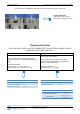
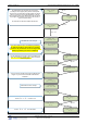
2011/11/10 Ed 1.5 Setup and Programming manual for XT series GPRS XT Programming Reset the XT Panel: Press and hold programming button () for 10sec until the Indicator LED blinks twice Press and instantly release the programming button (). The indicator LED will blink once. The panel is now in ‘Learn Mode’ for the CMA601 keypad. *Note: If you are having issues pairing the keypad to the panel, please refer to the troubleshooting section.
2011/11/10 Ed 1.5 Setup and Programming manual for XT series GPRS The Radio Range test should be run during device recording to ensure proper pairing with the control panel. This test is the communication strength between the device and the control panel. The keypad will display a real time RF level for the device that is being tested. This test will run until stopped and should be run for at least 30 seconds to receive accurate results.
2011/11/10 Ed 1.5 Setup and Programming manual for XT series GPRS YES DATE (Day) : 09/06/01 Use the or DATE (Day) : 09/06/03 to set the Day YES TIME (HOUR) : 00:00 Use the or TIME (HOUR) : 10:00 to set the Hour – The system uses a 24 hour clock.
2011/11/10 Ed 1.5 Setup and Programming manual for XT series GPRS CODE/STATE modification These are the default transmitted events: Device Alarm Alert Alarm Initialization Not Transmitted Panel Batteries Alarm/End AC Power Alarm/End Phoneline Fault Not Transmitted Tamper Alarm/End Device Batt.
2011/11/10 Ed 1.5 Setup and Programming manual for XT series GPRS Using the control panel as a Xtender system will only be able to arm and disarm by latching 9-12v to one of the two inputs. Arming input 1 will control the arming and disarming of devices in areas 1 and 2. Where devices in area 1 are subject to the Entry Delay. Arming input 2 will control the arming and disarming of devices in areas 3 and 4. Where devices in area 3 are subject to the Entry Delay.
2011/11/10 Ed 1.5 Setup and Programming manual for XT series GPRS GPRS PARAMETERS ? Your APN code (Access Point Name) is given to you by your YES to enter into the parameter and use the Keypad to complete the code. Press YES to confirm your entry and the arrow to move to the next APN CODE Cellular Provider. Press parameter. Your USERNAME is given to you by your Cellular Provider. YES to enter into the parameter and use the Keypad to complete the name.
2011/11/10 Ed 1.5 Setup and Programming manual for XT series GPRS During the GPRS Level test the Modem will boot and attempt to gain access to the internet to post a Level out of 5 or an error Code that will help troubleshoot why it cannot connect. To keep the keypad awake use any keys on the keypad except the YES, ESC/NO, and CLR keys. This test can take up to 5 minutes. Once the level or error has posted press YES to continue in programming.
2011/11/10 Ed 1.5 Setup and Programming manual for XT series GPRS Entering a Badge or Access Code for Arming/Disarming After Initial programming has been completed, you are not able to arm and disarm the system until you enter a user code or badge (the installer code cannot arm and disarm the system).
2011/11/10 Ed 1.5 Setup and Programming manual for XT series GPRS Changing Siren Options After initial programming has been completed any sounder on the system will be enabled by default, this includes the sounder on the Keypad and Badge Reader. While there is no way to disable the sounding of the exit delay you are able to disable the intrusion sound. Press the arrow to move to ACCESS LVL.
2011/11/10 Ed 1.5 Setup and Programming manual for XT series GPRS How to test to the dispatch center Testing to the dispatch is done twice during installation. Once while you are programming the system and then again once the installation has been completely finished. Although both will use the same steps the initial test will be just confirmation using one device to verify the programming. 10/12/27 10:53 DISARMED LVL:3 Enter a User code and press YES or present a badge to the reader.
2011/11/10 Ed 1.5 Setup and Programming manual for XT series GPRS How to Disable Monitoring Disabling monitoring can be a useful tool in many situations. Before mounting devices and moving the panel to find a good GPRS level, disabling monitoring will ensure that you will have access to programming and that unnecessary signals are not sent to the monitoring station.
11/11/10 Ed 1.5 Setup and Programming manual for XT series GPRS How to test GPRS for deployment of panel Before the system is mounted you will need to check the GPRS level to make sure it is adequate. If the level is 3/5 or better you can mount the control panel in that location. Press the arrow to move to MAINTENANCE. 10/12/27 10:53 DISARMED LVL:3 YES Press the MAINTENANCE arrow to move to GPRS LEVEL. Press YES on GPRS LEVEL to start the test.
2011/11/10 Ed 1.5 Setup and Programming manual for XT series GPRS How to test RF for deployment of devices Running the RF test during the mounting of devices is key to a successful Videofied installation. This test will ensure that all devices have adequate communication with the control panel. All Videofied devices are bi-directional which allows the system to ping the device and expect a response.
2011/11/10 Ed 1.5 Setup and Programming manual for XT series GPRS GPRS Antenna Connection ! WARNING ! Use caution before removing antenna connection. Damaged antenna connector is NOT covered under warranty. Using needle nose pliers, be sure to only grab the connector and pull directly up Arming Input Wiring Diagram HOST _ + When in Arm From Host mode the Videofied system will only arm and disarm when 9-12v is supplied and sustained.
2011/11/10 Ed 1.
2011/11/10 Ed 1.
2011/11/10 Ed 1.
2011/11/10 Ed 1.
2011/11/10 Ed 1.
2011/11/10 Ed 1.
2011/11/10 Ed 1.
2011/11/10 Ed 1.
2011/11/10 Ed 1.
2011/11/10 Ed 1.5 Setup and Programming manual for XT series GPRS How to enable the External RF Antenna The XTO 600/610 control panels have built in High Gain RF and GPRS antennas. The GPRS external comes pre-activated and hooked up, while the RF antenna is hooked up but needs to be activated in Configuration after you have completed initial programming. The following steps will walk you through how to enable the High Gain RF antenna after initial programming. Press the arrow to move to ACCESS LEVEL #.
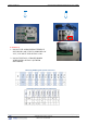
2011/11/10 Ed 1.5 Setup and Programming manual for XT series GPRS How to mount the XT600i/610 and XTX600/610 How to Mount the Control Panel? Fix the back casing on the wall with 3 screws () . How to Mount the XTO600/610 Included Mounting Hardware: Case and Mounting Screws, locking washers, bolts and nuts. Mounting Brackets 1. Install the Weather Resistant Wire Port.
2011/11/10 Ed 1.5 Setup and Programming manual for XT series GPRS 2. Place the cover on the base. 1. When closing the cover be sure to line up the two BOTTOM stickers face to face. 2. Be Careful not to slide the cover on. Instead come straight down in order to have the cover tamper properly seat. 3. Screw the cover to the base using the provided 8 screws. NOTE: To ensure proper functioning and to keep the case water proof you must mount the panel with the wire channel facing down. 4.
2011/11/10 Ed 1.5 Setup and Programming manual for XT series GPRS Troubleshooting Monitoring Station is not getting ANY video but is getting signals: Good communication between the MotionViewers and the Control Panel is key to getting successful video to the monitoring station. During mounting of any device on your Videofied system you must run the Radio Range/Device Locating test to ensure that the mounting location is with-in range of the Control Panel.
2011/11/10 Ed 1.5 Setup and Programming manual for XT series GPRS Monitoring Station is not getting any signals: Communication between the Control Panel and the Monitoring Station is over the GPRS side of the GSM cellular network. You will want to check your GPRS level to see if there is an error/level is too low. You must have a 3/5 or better for reliable transmission to the Monitoring Station. How to run the GPRS level test and GPRS error codes can be found on page 16.
2011/11/10 Ed 1.5 Setup and Programming manual for XT series GPRS Unable to record device or getting ‘Pairing Failure’ error This usually occurs when the device still has a pairing key from a previous system or setup. To perform a pairing key override: o o o o o 1. Remove all batteries from the device. 2. Make sure your system is ready to record devices: o A. If learning in the keypad, press the panel’s programming button. DO NOT HOLD THE PANEL’S PROGRAMMING BUTTON o B.
2011/11/10 Ed 1.5 Setup and Programming manual for XT series GPRS PROGRAMMABLE INPUTS CONFIGURATION Page 36 GENERAL PARAMETERS Page 37 Page 37 ALARM MODES PROGRAMMABLE RESPONDING PARTY LIST Page 38 AREAS AND DEVICES Page 39 CONFIGURATION MONITOR.
2011/11/10 Ed 1.5 Setup and Programming manual for XT series GPRS GENERAL PARAMETERS GENERAL PARAMETERS SITE IDENTIFICATION GPRS PARAMETERS PANEL PHONE NUMBER APN CODE NAME OR ADDRESS USERNAME XTENDER PASSWORD ARMING OPTION STANDALONE IP ADDRESS 1 0.0.0.0 ENTRY DELAY 000 DOMAIN NAME 1 TRANSMISSION DELAY 000 PORT 1 888 ARMING CONFIRMATION 0 IP ADDRESS 2 0.0.0.0 ARMING MODE SLOW DOMAIN NAME 2 PROGRAMMABLE OUTPUTS PORT 2 888 PROGRAMMABLE OUTPUT 1 TMT IP ADDRESS 0.0.0.
2011/11/10 Ed 1.
2011/11/10 Ed 1.
2011/11/10 Ed 1.5 Setup and Programming manual for XT series GPRS CONFIGURATION MONITOR. STATION CONFIGURATION MONITOR. STATION MONITORING PARAMETERS MONITORING ENABLED ACCOUNT NUMBER PERIODIC TEST PERIODIC TEST 24 HOURS TEST HOUR 15:00 SYSTEM ARMED DISABLED ALARM CODES TRANS.
2011/11/10 Ed 1.5 Setup and Programming manual for XT series GPRS Addendum 1. LSH20 Control Panel Batteries: 2. LS14500 Peripheral Batteries: Excludes SE601 and SE651 3.
2011/11/10 Ed 1.5 Setup and Programming manual for XT series GPRS 4. Finding Manufacture Week and Year: The Manufacture week and year can be found in the serial number of the device/control panel. The second sets of 4 numbers in the serial number are WWYY. ####0411######## = Which shows that this device was manufactured in the 4th week of 2011.