
Installation Instructions

Mounting
>
Use proper tools and hardware for mounting the unit.
>
Mount outdoors under eves to help prevent direct contact
from elements.
>
Mount on front of structure where strobe light is clearly
visible to responding authorities.
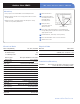
1
Remove batteries.
2
Hold unit up against
mounting surface and
mark the three
mounting holes.
3
Drill pilot holes
and install anchors
where needed.
4
Place unit on mouning surface so mounting holes
line up with pilot holes/anchors and secure unit with
appropriate screws.
5
Install batteries, observing correct polarity.
6
Place the flash wire of the cover to the siren.
7
Attach front cover.
Electrical Data
Panel Compatibility XL, Visio, XT, XTIP
Power requirements Four 1.5 V Alkaline Batteries
Nominal Voltage 6V
Low Battery Limit 4.8V
Battery type Energizer Alkaline D cell - LR20
Battery life Up to 4 years
RF technology S
2
View
®
Radio type Spread Spectrum Bidirectional
Operating frequency 915 MHz
Transmission security AES encryption algorithm
Supervision Polled signal every 8 minutes
Antenna Integrated
Tamper detection Wall and cover tampered
Speaker impedance 4 ohms
Output level 105 dB @ 1 meter
Output duration Configured in Control Panel
Flash type Strobe light tube
Flash duration Matches Programmed Siren Length
Flash sequence Four flashes/sec
Operating temperature -30°/+60°C (-20°/+140°F)
Maximum relative humidity 90%, non-condensing
Approvals FCC Part 15C
Physical Data
Material ABS—ULV0
Dim ensions 227 mm x 166 mm x 80 mm
(LxWxD): 9 in. x 6-1/2 in. x 3 in.
Weight 880 g/31 oz. (without batteries)
Installation/Mounting
Unit/Base Four screws secure unit to base; three screws
secure unit base to mounting surface.
www.videofied.com
Mounting Holes
INSTALLATION DATA SHEETOutdoor Siren SE651