
User Manual

Programming/RF Testing/Mounting
The following provides summarized steps for device programming,
testing, and mounting. For complete details, refer to the control panel
installation manual.
1
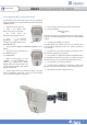
Separate the base from the box
2
Install 3 3.6V LS14500 SAFT
batteries observing correct polarity.
3
Put control panel into
Programming/Configuration mode.
4
Using a programmed
alphanumeric keypad, proceed
through menus until the display shows
ADD A NEW DEVICE.
5
Press OK/YES. the display shows PRESS PROGRAM BUTTON OF
DEVICE.
6
Press and release program button on
the OMV MotionViewer.
The OMV PIR flashes.
7
Wait for keypad display to show
CAMERA(1 - 25) PROGRAMMED. Press
OK/YES, the display shows RADIO
RANGE TEST? Press OK/YES again. The
camera LED starts flashing and keypad
display shows RF TEST.
8
Take the OMV camera to its intended mounting location and
make sure LED flashes continuously or you receive a 9/9 indicating
good communication with the control panel.
9
Press OK/YES to end radio range test then press ESC/NO.
10
The keypad displays :
AREA ALLOCATION :
AREA : 1
Press either arrow button repeatedly until desired area number appear
then press OK/YES. By default all devices in Area 1 are automatically
delayed.
11
The display shows NAME + LOCATION:
Enter appropriate device name/location (up to 16 characters), then
press OK/YES. The display shows the device number and name for
your verification.
12
Mount the DCV on the wall or the MB 110 Mounting kit. Follow
the installation guidelines shown in page 1.
13 Press OK/YES. The display shows FUNCTIONAL DEVICE TEST?
Press OK/YES and verify camera operation. For example, wave your
hand in front of the sensor to activate its LED indicating detection.
14 Press OK/YES to end detection verification.
15 The display shows OPERATION COMPLETED or ADD A NEW
DEVICE? Press YES/OK. Repeat steps 1 – 14 for remaining cameras.
16 When finished, exit from configuration mode.
Screw
IN IT button
2
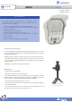
INSTALL SHEET
OMVC OUTDOOR MOTION VIEWER