
Installation Instructions

Mounting
>
Use proper tools and hardware.
>
Mount indoors in a temperature-controlled environment.
>
Mount detector on frame and magnet assembly on movable
opening (door, window).
>
When using internal switch, mount so that detector and
magnet alignment marks are lined up with each other.
>
When using internal switch, do not exceed 10 mm (3/8”)
gap between detector and magnet.
>
Magnet spacers must be used to match magnet height with
detector to ensure correct alignment and functionality.
Note: If detector installation only requires use of the external input,
magnet assembly installation is not required.
1
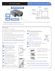
Separate base from detector.
2
Hold detector base against
mounting surface and mark
the two mounting holes.
3
Drill pilot holes into mounting
surface.
4
Mount detector base to surface
using appropriate screws.
5
If using external input, run
2-conductor, 22-gauge wire from
protection point to detector.
6
Connect hardwire circuit wires to
external input screw terminals.
7
Connect other end of wires to
initiating device and install the
battery.
8
Attach detector to base, making
sure every wire is secure with screws.
9
Attach wedges to magnet holder
as needed to match height of detector.
10
Hold magnet base against
mounting surface and mark
the two mounting holes.
Note: Be sure alignment marks on detector
and magnet base are lined up with each other
and that there is no more than a 10 mm (3/8”)
gap between them.
11
Drill pilot holes into mounting surface.
12
Insert screws through magnet base and wedges,
then secure to mounting surface.
13
Attach cover to magnet holder.
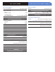
External Input Terminal, Jumper position and wiring
Note: The internal jumper wire is only used for internal or external
switch use. The jumper is not used when both Int. and Ext switches are
used together. The default jumper position is in the Internal switch mode.
it only has to be changed if wiring external switches to the transmitter.
The internal jumper shown in
position for possible connections.
1. Internal reed switch only
2. External reed switch only
3. Both Int. and Ext. switch use
>
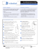
For the magnet to have proper detection, it must be positioned on the high part of the contact facing the ILS, use the supplied
wedges if needed. (see the diagram opposite).
>
Magnet should always be positioned on the mobile part.
Three axis movement detection
Internal Reed Switch
External Reed Switch
Int + Ext Reed Switch
External
Input
Terminals
To
Initiating
Device
Mounting
Holes
Base
Wedge
Indicator
The markers must be lined up
Magnet +
wedges
PROGRAM Button
1 cm max.
PRODUCT INSTALLATION SHEETDoor Contact CT601