
User's Manual
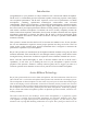
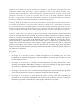


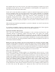
Table Of Contents
- TABLE OF CONTENTS
- Model R-122V Vacuum Tube Ribbon Microphone
- Introduction
- Active Ribbon Technology
- Description
- Applications
- Ribbons in the Digital World
- User Guide
- Using the R-122V vacuum tube Ribbon Microphone
- Power Supply Input Module
- Operation
- Amplification Considerations
- The Sweet Spot
- Finding and Working with the Sweet Spot
- Proximity Effect and Working Distance
- The Sound That Is “More Real than Real”
- Microphone Techniques
- General Tips for Using the Royer R-122V
- Stereophonic Microphone Techniques
- Specialized Recording Techniques
- Recording on the Back Side of the R-122V
- Care & Maintenance
- Troubleshooting
- Features
- Electrical Specifications
- Mechanical Specifications
- Polar Pattern
- Frequency Response
- Warranty

extending the life of the tube. We recommend letting the R-122V warm up for at least 15
minutes prior to use. When the microphone becomes operational, bring the channel fader to
0-dB (unity) and use the trim to set the desired level. This technique maximizes the signal-to-
noise performance of the preamplifier or console input channel.
5. When disconnecting the microphone, bring the channel fader down, turn the R122V's power
supply OFF and unplug the microphone cable from the power supply.
6. If the studio has the microphone lines brought to a patch bay (tie lines), never crosspatch a
microphone line when phantom is applied or the monitor volume is raised. This could cause
damage to your monitor speakers or, if passive ribbon microphones are involved, it could
cause ribbon failure.
Power Supply Input Module
The power OFF/ON switch and the Power Input Module
are located on the rear side of the power supply (Image
1). The Power Input Module (Image 2) serves multiple
functions, and is integral to the design of the power
supply. It serves as a means to connect and remove the
AC mains cable, it houses the AC line fuses, provides a
convenient method of voltage changeover, and also
serves as an RF line filter.
AC power is supplied to the unit via a removable IEC
type business machine cable that plugs into the bottom
section of the Power Input Module. The power cord must
be removed to gain access to the door to change fuses or set the unit to a different AC input
voltage.
Fuse replacement
Two fuses are used to protect the circuitry of the power supply, one
on each side of the mains line. To inspect or replace the line fuses
(necessary when changing voltage settings), first remove the power
cord. Insert a medium size flat-blade screwdriver into the lip at the
top of the module and gently pry the door open (Image 3). Be
careful not to damage the The fuses are located inside two carriers,
each marked with an arrow pointing to the right. These carriers can
be pulled out with the tip of a screwdriver blade or a pair of needle
nose pliers (Image 4). Once the carriers are removed, the fuses can
be pulled out with your fingers. Replacing the fuse carriers is the
reverse of removal. They can only be inserted with the arrow facing
to the right and they should go in very easily.
CAUTION!
7
Image 1
Image 2