MODEL:RSH-380SL Roll Laminator Service Manual
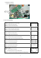
Table of Content 1.Safety Precautions ……………………………………………………………………… 3 ~ 3 2.Troubleshooting …………………………………………………………………………… 4 ~ 10 2.1) Rollers Not Heating ………………………………………………………………………… 4 ~ 6 2.2) Rollers Over Heating …………………………………………………………………………6 ~ 7 2.3) Rollers Not Running ………………………………………………………………………… 7 ~ 9 2.4) No Main Power …………………………………………………………………………………9 ~ 10 2.5) Poor Lamination Quality …………………………………………………………………… 11 ~ 11 3.Replacing Parts ……………………………………………………………………………… 12 ~ 14 3.
1. Safety Precautions Failure to comply any of the following safety procedures could result in serious injury. Please read the instructions carefully and keep for future reference. 1. Only a licensed electrician should install wiring and outlet for the laminator. 2. Ensure the unit is plugged into a properly grounded outlet with the correct voltage. 3. Keep hands and clothing(ie.Neckties)away from rollers. The rollers are pinch points that can trap body parts or clothing and cause serious injury .
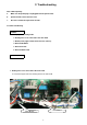
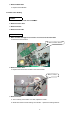
2. Troubleshooting Note: While repairing: a. Make sure the power plug is unplugged from the power outlet. b. Open both side covers and rear cover. c. Be sure to follow the steps below in order. 2.1 Rollers Not Heating CAUSES: 1. Improper laminating mode. 2. Heating wire is not connected to the main PCB. 3. Blown (burnt) upper and/or lower wire fuse (T/Fuse). 4. Defective Bi-Metal. 5. Defective heater. 6. Defective Main PCB. MEASURE 1. Heating wire is not connected to the main PCB. a.
2. Blown (burnt) wire fuse (T/Fuse). a. Replace the T/Fuse wire located on the left-hand side. Wire-Temp. Fuse 3. Defective Bi-Metal. a. Replace the Bi-Metal Bi-metal (135℃) 4. Defective heater. a. Using the multi-meter, test the continuity of the heater. If it fails, replace the heater. Multi-meter b. Physically examine the heater assembly for breakage.
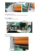
5. Defective Main PCB. a. Replace the PCB Main. 2.2 Rollers Over Heating CAUSES 1. Heat sensor is reversed on the PCB Main. 2. Defective T/Fuse wire. 3. Defective heater. 4. Defective main PCB. MEASURES 1. Wires for lower and upper heat sensors are reversed on the main PCB. a. Reverse the heat sensors. Connector-Wire Sensor 2. Defective T/Fuse wire. a. Replace the T/Fuse wire located on the left-hand side. Wire-T / Fuse 3. Defective heater. a. Test continuity of the heater.
4. Defective Main PCB. a. Replace the PCB Main. 2.3 Rollers Not Running CAUSES 1. No power to the unit. 2. The main switch is close. 3. Opened safety cover. 4. Film is jammed on the rollers. 5. Disconnected motor wire. 6. Defective main motor. 7. Defective main PCB. MEASURES 1. No power to the unit. a. Make sure the power plug is connected to the proper source of outlet 2. The main switch is close. Main Switch 3. Opened safety cover. a.
Switch is engaged 4. Film is jammed on the rollers. a. Un-jam the film using a combination of the pressure lever and reverse button. 5. Disconnected motor wire. a. Check the motor wire connection with PCB. Wire-motor 6. Defective main motor. a. Replace the main motor.
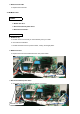
7. Defective main PCB. a. Replace the main PCB. 2.4 No Main Power CAUSES 1. No electricity. 2. Blown main fuse. 3. Disconnected main power wires. 4. Defective transformer. MEASURES 1. No Electricity. a. Double check to insure that you have electricity from your outlet. b. Check the circuit breaker. c. Double check that source of power is 220V, 15Amp, and single phase. 2. Blown main fuse. a. Replace the main fuse located above the main power switch. Main Fuse 3. Disconnected main power wires. a.
4. Transformer is defective a. Replace the transformer. Transformer 2.5 Poor Lamination Quality Problem: Straight wave lines across the output. Cause: Excessive front roller pressure. Measure: Loosen the front roller pressure. Problem: Concave waves in the lamination. Cause: Excessive rear (pulling) roller pressure. Measure: Loosen the rear back roller pressure. Problem: Angled waves on both sides of the output. Cause: Insufficient rear roller pressure. Measure: Tighten the rear roller pressure.
3. Replacing Parts Note: While replacing parts: a. Make sure the power plug is unplugged from the power outlet. b. Open both side covers and rear cover. 3.1 Replacing the Right Cover. a. Take out the pressure lever (Figure 1) and four cover screws using Phillips screw driver (Figure 2). Figure 1 Figure b. Pull out the male control panel connector from the Sub-PCB( Figure 3). Figure 3.2 Replacing the Sub-PCB a. Refer to “Replacing Right Cover”. c.
3.4 Replacing the Heaters Note: Cotton or surgical gloves are recommended while handling the heater assembly. a. Disassemble Right and Left Covers (Refer to “Replacing Right Cover” and “Replacing Left Cover”). b. Take out the heater brackets on each side by loosening screws (Figure 8, 9). Figure9 Figure8 c. Take out the broken heater. Figure 10 Figure 1 Note: a. When inserting the heater into the roller, rotate the heater slightly and push the rod in gently. b.
4. Adjustments C.W C.C.W .2 Adjusting front and rear rollers Pressure • Use Screwdriver to adjust the roller pressure: C.W – Increase pressure. C.C.W – Decrease pressure. 1.Using Push-Pull Scale , measure 3 spots as shown on Figure B &C: Figure A Front roller should be 5~6 and back rollers should be 6~8. 2.Checking for over all tension – when the machine is running, check that the top and the bottom films are fed in without any wrinkles. 3.
5.PART LIST No. Part No. Part Name Spec. 1 021LR0001A COVER-L ABS PA-765 UL94 V-0 PANTON 431 2 125LR4001A HANDLE-TENSION S45C Cu+Ni+Cr 3 138LR4012A SPRING-TENSION SWP Ф3.2 4 12200X022A BEARING-RADIAL 15*28 5 141LR4033A PLATE-PRESSURE,PULL SPCC 3.0T 6 138LR4015A SPRING-PRESSURE SWP Ф2 7 141LR4032A PLATE-PRESSDURE,LAMI SPCC 3.0T 8 141LR4035A PLATE-DU BUSH SECC T=2.0 9 141LR4019A BRACKET-HEATER,UP SPCC 1.
35 141LR4043A FRONT TABLE SAFETY LEVER SPCC 1.5T 36 013LR4004A SAFETY FRAME SPCC 37 021LR3024A SAFETY-COVER PC 3.0T 38 014LR3001B TABLE-FRONT AL6063 39 133LR3001A ROLLER-LAMI STPG ORG 40 223LR3001H HEATER ASS'Y FCHW1 81Ω EU,KR,CH,EU(N),BR 40-1 223LR3001J HEATER ASS'Y FCHW1 96Ω AU,UK 40-2 223LR3001E HEATER ASS'Y FCHW1 24Ω CUL 40-3 223LR3001D HEATER ASS'Y FCHW1 20.2Ω TW 40-4 223LR3001F HEATER ASS'Y FCHW1 16.
68 350LR3043A PCB-SUB ASSY FR-4 69 36600X001A FUSE-BLOCK FB66 LITTLE FUSE TRIAD INC 70 32500X0008 FUSE-MAIN 65TS AC250V 10A EU,AU,KR,CH,UK,EU(N),BR 70-1 32500X0005 FUSE-MAIN 65TS AC250V 20A TW,CUL,JOL,JAP 71 021LR3018A COVER-R ABS PA-765 UL94 V-0 PANTON 431 72 138LR4001A SPRING-CUTTER CROSS SWRH Φ0.
6.
7. Wire Diagram 1 2 3 4 5 VCC_5V VCC_5V CA RB ON S/ W 6 7 VCC_5V 8 VCC_5V SW1 U101 PIC16C72 C106 3.
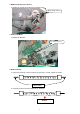
5 2 8 7 4 1 3 6 1. Wire Main. 6. Wire Power Transformer In 2. Wire Power 7. Wires Power Transformer Output 3. Wire Heater,up 8. Wire Fuse 4. Wire Heater,low 5.
SUB PCB Bimetal(135℃) Wire Sensor Fuse Main Power Cord Wire Bimetal Motor Wire Lo Heater Wire Up Heater 18
Wire T/Fuse (133℃) Micro Switch Wire Safety S/W Wire Motor 19