Assembly Instructions ITM. / ART. # TM21RD41FPT1 IMPORTANT, RETAIN FOR FUTURE REFERENCE: READ CAREFULLY THE ITEM IS INTENDED FOR OUTDOOR DOMESTIC USE ONLY, NOT FOR COMMERCIAL USE. Fire Table Questions, problems, or missing parts? Before returning to the store please visit sunvilla.com, or contact our Customer Service Department at cs@sunvillahome.
CONTENTS • Warnings ................................................................ 1-4 • Diagram ................................................................... 5-6 • Assembly ................................................................ 7-8 • Operation ................................................................9-10 • Maintenance & Storage ................................... ...... 11 • Trouble Shooting ....................................................
Page 1 of 14 Warnings DANGER CARBON MONOXIDE HAZARD ● This appliance can produce carbon monoxide which has no odor. Using it in an enclosed space can kill you. ● For outdoor use only. ● Never use in the unventilated or enclosed areas. IF YOU SMELL GAS: ● Shut off gas to the appliance. ● Extinguish any open flame. ● If odor continues, keep away from the appliance and immediately call your gas supplier or fire department for help.
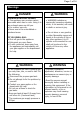
Page 2 of 14 Warnings WARNING ● The installation of this unit must adhere to local codes or either the National Fuel Gas Code, ANSI Z223. 1/NFPA54, OR CAN/CGA- B149.1, National Gas and Propane Installation Code. ● This unit is to be used with propane gas only! (sold separately), is not intended for natural gas. ● Do not use any solid fuel or charcoal for this unit. ● Do not use any more than 1/4in depth lava rocks/ pumice stones/ Lava Glass above the burner holes. Doing so will suffocate the flame.
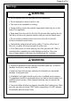
Page 3 of 14 Warnings WARNING ● DO NOT add water into the unit. ● DO NOT disconnect any part while the unit is in use. ● DO NOT operate on a boat or vehicle. ● DO NOT set the Protective Cover over the unit until the Fire Table / Column is turned off and completely cooled down (where applicable). ● Check for leaks after not using the unit for long periods of time. WARNING ● All installation and repair should be done by a Qualified Service Technician.
Page 4 of 14 Warnings WARNING ● Do not operate unit until all parts are fully assembled. ● Do not attempt to move it while in use. ● This unit is not intended for cooking. ● Young children should be carefully supervised when they are in the area of the appliance. ● Keep away from the unit for the first 20 minutes after igniting for the first time, as lava rock /pumice stones could pop out and cause injury.
Page 5 of 14 Parts Diagram Item Picture Description Qty 01 Guard 1 02 Themocouple 1 03 GroundWire 1 04 Ignition Pin 1 05 Burner Plate 1 06 Main Frame of Fire Table 1 07 Lava Rock 4 08 Burner 1 09 Nozzle 1 10 Corrugated Pipe 1 11 Swithing Valve 1 12 Regulator Valve with Gas Hose 1 13 Control Knob 1 14 Igniter 1 15 Foot 4 16 Warning Label 1 17 Wing Screw with Nut 1 18 Metal Stand 1
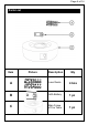
Page 6 of 14 Parts List Item Picture Description Qty A Lava Rocks 4 box B AAA Battery 1 pc C Main Frame of Fire Table 1 pc
Page 7 of 14 Assembly Instructions Step 1: Check that the control knob (13) for the gas supply system is turned to the “OFF” position before starting any assembly. 13 1 Step 2: Place a 20 lbs Propane Gas Tank (not included) into the Metal Stand (18). 2 Make sure the Propane Gas Tank is placed completely into the Metal Stand. Turn the preassembled Wing Screw (17) in a 5 clockwise direction in to the Nut to secure the Propane Gas Tank tightly.
Page 8 of 14 Assembly Instructions Step 4: Remove the Electronic igniter Cap on the Electronic igniter (14) by unscrewing and slide the Battery (B) into the battery slot. Make sure the positive side of the Battery (B) faces outwards. Screw the Electronic Igniter Cap (14) over the battery,tightly. Step 5: pour Lava Rocks over the Burner Ring. The Guard MUST NOT BE BLOCKED. Do not place more than 1/4 inch depth of lava rocks above the burner holes. Do not place more than 26.
Page 9 of 14 Operation FOR YOUR SAFETY, READ BEFORE LIGHTING • Before performing a leak test, make sure that no sparks can occur and you are in a spacious outdoor area. • Connect the propane gas tank to the regulator and turn the valve on the unit to the “off” position. • Brush a soap and water mixture on all connections. • Make sure the igniter battery has been installed properly. The igniter will not operate otherwise.
Page 10 of 14 Operation Using Your Fire Table 1. Make sure the Control Knob (13) is in the “OFF” position. 2. Open the Door and slowly open the Valve (22) on the Propane Gas Tank by turning the Control Knob (13) counterclockwise. 3. Close the Door on the Main Frame (06) of the Fire Table. 4. Push and hold in the Electronic Ignition to create sparks within the electrode continue to hold. 5. Push in the Control Knob (13) and turn to the “LOW” position.
Page 11 of 14 Maintenance & Storage To enjoy years of outstanding performance from your heater, make sure you perform the following maintenance activities on a regular basis: • Before performing any maintenance always disconnect propane gas tank. • Use warm soapy water for cleaning. Never use flammable or corrosive cleaning agents. • DO NOT use petroleum-based or abrasive cleaning products. • DO NOT use any harsh brushes/rough sponges when cleaning the Fire Table/Column surface.
Page 12 of 14 Trouble Shooting PROBLEM Burner will not light using igniter Burner will not light with match The fire table emits a lot of black smoke when in use Sudden drop in gas flow, or a reduced flame height CAUSE Electrode and burners are wet SOLUTION Wipe dry with cloth. Igniter battery is dead or backwards Check that the battery is inserted correctly in the igniter or replace the battery. Make sure the plastic wrap on the battery has been removed.
Page 13 of 14 Trouble Shooting Problem: Burner JUST LIGHT UP FOR SECOND AND WILL AUTOMATICALLY TURN OFF PILOT GUARD 1 2. 3 . THERMOCOUPLE IGNITION PIN 4 . IGNITION PIN THERMOCOUPLE 1. The thermocouple will be under the Pilot Guard on the top of the unit. Please remove the Pilot guard by unscrewing it from the metal bowl with a screw driver. 2. Once the Pilot Guard has been removed, you will have two components exposed; the copper one is your thermocouple.
Page 14 of 14 Warranty Information This product has been manufactured under the highest standards of quality and workmanship. We warrant to the original consumer that all aspects of this product will be free of defects in material and workmanship for one year from the date of purchase. A replacement for any defective part will be supplied free of charge for installation by the consumer. Defects or damage caused by the use of other than genuine parts are not covered under this warranty.