
User manual


BlueSentry User Manual
www.rovingnetworks.com
BlueSentry-um Version 1.0 3/12/2010
809 University Avenue • Los Gatos, CA 95032 • Tel (408) 395-6539 • info@RovingNetworks.com
~ 9 ~
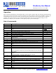
The output rate is set by 18000 / (D), where D is the delay value Standard delay values set by the + and – , and
f commands are:
CHAN DELAY MAX ASCII DELAY MAX FAST
ACSII
DELAY MAX
BINARY
1 0X0018 750 Hz 0X0012 1000 Hz 0X0009 2000 Hz
2 0X0030 375 Hz 0X0024 500 Hz 0X0012 1000 Hz
3 0X0048 250 Hz 0X0036 333 Hz 0X001B 750 Hz
4 0X0060 187.5 Hz 0X0048 250 Hz 0X0024 500 Hz
For example, to set a rate of exactly 200Hz, D = 90 decimal, or 005A hex. So you would type “d005A” to set that
delay value. The hex value 0x4650 = exactly 1 second rate. The fastest rate possible is 3Khz, in FAST BINARY
mode, with a delay value of 0x0006
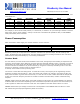
Power Consumption
When connected to 5VDC supply, the module draws the current as shown:
Sate BT not connected BT connected
Idle 20mA 40mA
Fast AD 60mA
Sleep mode 7mA
BlueSentry can be put to sleep with the ‘s’ character command. The processor stops, And all circuits go low
power. The Bluetooth radio will disconnect, then stay awake to listen for incoming connections. The unit can be
awakened from sleep automatically by re-connecting via Bluetooth.
Counter Mode
For each channel, a counter mode can be enabled. In this mode, the high byte of the reading is compared to the
previously stored reading. If the difference is greater than the threshold (default is 0x80, or 2.5Volts) a counter is
incremented. The result will be sent as ABXX, where AB is the count from 0 to 255, and XX should be ignored.
Counter mode can be enabled for any of the channels, by using the K command, and setting a bit to 1 for each
channel. For example, if counter mode on channels 0 and 2
is desired, set the mask to 0x05 by sending “k05”.
The counter is reset after each delay period. To utilize this counter, the frequency of the signal being counted
divided by the delay value should be < 255 or the counter will overflow. For example, if the signal is 1KHz, the
delay value should be no greater than 0.25 second, or a hex value of 0x1194 or faster. Because the sample rate
is 5Khz, the maximum frequency that can be counted is limited to around 2.5Khz/ number of channels being
sampled.
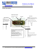
POWER1 supplies the clean 5VDC output of the LDO regulator to load circuits via a power MOSFET. The LDO has
an 800ma load current limit and depending on the environment temperature may have a lower thermal drop out
as the regulator on board does not have a heat sink. The impedance of the FET switch is about 0.1 ohms.
POWER2 switches the input voltage to load circuits. The impedance of this MOSFET switch is about 0.1 ohms.
IO1 and IO2 are general purpose digital IO (25ma current limit).