
User manual


BlueSentry User Manual
www.rovingnetworks.com
BlueSentry-um Version 1.0 3/12/2010
809 University Avenue • Los Gatos, CA 95032 • Tel (408) 395-6539 • info@RovingNetworks.com
~ 4 ~
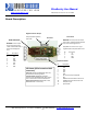
Board Description
RJ45 Connector
WARNNG: Channel inputs
must not be driven above
+5VDC and below 0V GND, or
permanent damage will
occur
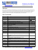
Pin Description
1 V+
2 CH5
3 CH3
4 CH4
5 GND
6 CH6
7 CH7
8 CH8
8
7
6
5
4
3
2
1
4 3 2 1
Screw Posts
WARNNG: Channel inputs must not be
driven above +5VDC and below 0V GND,
or permanent damage will occur.
Apply 6VDC or more on Pin 1 to get
regulated power output of 5VDC on JP1
Pin Description
1 V+
2 CH1
3 CH2
4 GND
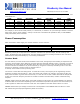
Expansion Header
Pin Description
1 CH 3
2 CH 4
3 CH 5
4 CH 6
5 CH 7
6 CH 8
7 IO 1 General purpose digital IO
8 IO 2
9 POWER 1 switches 5VDC to load circuit
10 POWER 2 switches VIN to load circuit
11 VIN power input
12 System GND
1 2 3 4 5 6 7 8 9 10 11 12
LED Status (LEDs located on RJ45
connector)
Power Up: YELLOW and GREEN LED alternate
about 10 times indicating self test
Connected State: GREEN LED will blink 4
times/second, YELLOW LED blinks when data is
sent or commands received over Bluetooth
Failed internal self test: YELLOW LED is solid,
GREEN LED blinks continuously
Not Used
2 1
Regulated Power Output
Pin1(JP1)=5VDC regulated,
Pin2=GND