
User manual


BlueSentry User Manual
www.rovingnetworks.com
BlueSentry-um Version 1.0 3/12/2010
809 University Avenue • Los Gatos, CA 95032 • Tel (408) 395-6539 • info@RovingNetworks.com
~ 10 ~
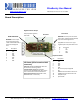
Access to regulated 5VDC output power
In some cases it may be useful to tap the 5VDC regulated power used internally by the BlueSentry. This power is
available on Jumper JP1 pin 1, which is the square pin (pin 2 is GND). 5VDC is also available on Pin 1 of the 8 pin
box header, J4, pin 1 has the small white arrow pointing to it.
BlueSentry Example:
The following example illustrates some of the features of the BlueSentry with screenshots to familiarize you with
its capabilities.
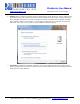
1. Connect to the BlueSentry as described in the “Connecting over Bluetooth” section.
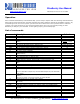
2. Once the connection is made, the BlueSentry will start displaying data from sensor inputs. By default, it
shows the data of the first four channels (Channel 1 through 4). The first column is the sequence number
and the next four columns is the data output from the four channels
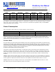
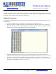
3. To switch to differential mode, use the “m” command. Default setting is single ended, wherein the
channels are referenced to ground. In differential mode, the channels are paired, 1-2, 3-4, 5- 6, 7-8 and
the resulting measurement is the delta between the channels. The first channel is + and the second
channel is -. In our case, since we have 4 channels being displayed, after the “m” command, we will have
two channels being displayed at output (1-2 and 3-4).