RN Commands Version 4.25, 11/1/2007 Page 1 of 25 User Guide For: ™ ® Roving Networks Bluetooth Serial Module Command Set As applied to RN-21/22/24, and RN-41 Bluetooth Modules, BluePort-XP, FireFly Serial Adapter Version 4.26 October 19, 2007 Roving Networks, Inc.
RN Commands Version 4.25, 11/1/2007 Page 2 of 25 1 INTRODUCTION....................................................................................................................................................................................3 2 MODES OF OPERATION ..................................................................................................................................................................5 3 CONFIGURATION...........................................................
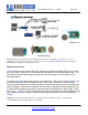
RN Commands Version 4.25, 1 11/1/2007 Page 3 of 25 Introduction Scope: This Command Set document along with the RN-21/41 (class 1), RN22/24 (class 2), and the FireFly™ evaluation board are created to enable developers and integrators an opportunity to create wireless networks using Bluetooth technology. The goal is to make the transition to Bluetooth wireless networks as seamless and easy as possible.
RN Commands Version 4.25, 11/1/2007 Page 4 of 25 RN-24 module RN-41 Module FireFly Adapter Note: Applications that require the embedded device not the PC to manage the connection process for 7 simultaneous connected remote devices you will need to license the Roving Networks reference design and Bluetooth stack software for embedded pico-nets.
RN Commands Version 4.25, 11/1/2007 Page 5 of 25 2. Modes of Operation 0- Slave mode – This is the default mode, whereby other Bluetooth devices can discover and connect to the device. Outbound connections can also be made in this mode. 1- Master Mode - This mode is useful when the device only wants to initiate connections (not receive them). In this mode the device will NOT be discoverable or connectable.
RN Commands Version 4.25, 11/1/2007 Page 6 of 25 3. Configuration Command Mode (vs Normal Data mode)- Upon powerup, the device will be in data mode. To enter command mode, The characters “$$$” must be sent. The device will respond with “CMD”. To exit command mode, send “---”. The device will respond with “END”. Parameters, such as the Bluetooth Name, Class of Device and Serial Port settings can be viewed and configured.
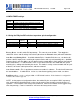
RN Commands Version 4.25, 11/1/2007 Page 7 of 25 CONFIG TIMER settings VALUE (decimal) 0 1-252 253 254 255 DESCRIPTION No remote config, No local config when connected Time in seconds from powerup to allow config Continous config LOCAL only Contiuous config, REMOTE only Continous config, both LOCAL and REMOTE 3.
RN Commands Version 4.25, 11/1/2007 Page 8 of 25 4. Command Reference The commands are all single or 2 character, generally comma delimited. Commands and hex input data can be upper or lower case. Text data, such as Bluetooth name, and pin code, are case sensitive. Commands fall into 4 general categories: SET COMMANDS - store information permanently and take effect after power cycle or software reset. GET COMMANDS -retrieve the permanently stored information for display to the user.
RN Commands Version 4.25, 11/1/2007 Page 9 of 25 Maximum value is 0x1000, set to 0x0000 to disable inquiry scan and make device nondiscoverable. Default value is 0x0200. SJ, - - Page Scan Window. Sets amount of time device spends enabling page scan (connectability) . Minimum value is 0x0012, corresponding to about 1% duty cycle. Page Scan interval is fixed at 0x1000, so time spent in page scan mode is 0x12/0x1000 by default.
RN Commands Version 4.25, 11/1/2007 Page 10 of 25 Example : “SS,SerialPort” ST, - Config Timer, # of seconds ( range= 0 to 255 decimal,, default = 60 decimal) to allow remote configuration over Bluetooth after power up in Slave Mode. In all Master modes, the remote config timer is set to 0 (no remote configuration). In Trigger Master Mode, this Timer is used as an Idle timer to Break the connection after the timer expires with no characters being received.
RN Commands Version 4.25, Example : “GS” 11/1/2007 Page 11 of 25 will return 1 or 0 depending on the value of security. In addition to the above, there are a few other useful commands available . GB GK G& V - returns the Bluetooth Address of the device. returns the current connection status: 1=connected, 0 = not connected.
RN Commands Version 4.25, 11/1/2007 Page 12 of 25 IR
RN Commands Version 4.25, 11/1/2007 Page 13 of 25 COMMANDS to MANIPULATE GPIO CMD @ & % ^ * VALUE DESCRIPTION Set direction bits for GPIO Set values for GPIO Store powerup direction bits for GPIO Store powerup values for GPIO Set values for PIO8,9,10,11 The GPIO command interface uses combination of 2bytes, a mask, and value, packed into a hex word for each command.
RN Commands Version 4.25, Examples: S*,0101 S*,0100 S*,0202 11/1/2007 Page 14 of 25 GPIO-8 driven HIGH. GPIO-8 driven LOW. GPIO-9 driven HIGH. 4. 1 Using Low Power Modes 4.1.1 Inquiry(Discovery) and Page(Connection) Windows There are 2 timers that can be used to lower the idle Slave mode power of the radio. When not connected, the Radio is active for a percentage of time listening to see if any other device wants to Discovery (inquire) or Connect (page).
RN Commands Version 4.25, 11/1/2007 Page 15 of 25 Deep Sleep mode can be used to obtain extremely low power operation. The device totally shuts down and only draws about 300uA of current in this mode. To enable Deep Sleep, set the high order bit of the Sniff word = 0x8000. This bit is NOT used to determine the sleep interval, it is only used as a flag to enable deep sleep. For example, If you want ½ second sleep 0x0320, with Deep sleep, you would set the sniff word to 0x8320.
RN Commands Version 4.25, 11/1/2007 Page 16 of 25 The default profile is Serial Port Profile (SPP). The firmware also supports the DUN profile in both master and slave modes. To change the profile, use the “S~,” command. Profile: 0 1 2 3 - Default SPP. (no modem control) DUN DCE (slave or gateway). DUN DTE ( master or client). MDM SPP with modem control signals. The most common use of DUN profile is to enable a BT client to connecti to a dialup modem.
RN Commands Version 4.
RN Commands Version 4.25, 11/1/2007 Page 18 of 25 K, - Kill (disconnect) from current connection Q - Turn off Discovery and Connectability R,1 - Reboot T,<0,1> - Pass receive data (from uart or BT) while in command mode. U,, - Temp Uart Change & - return the value of the DIP Switches Z - Enter low power Sleep mode 809 University Avenue • Los Gatos, CA 95032 • 1-(408) 395-6539 • info@rovingnetworks.com www.rovingnetworks.
RN Commands Version 4.25, 11/1/2007 Page 19 of 25 6 Factory Default Power up Settings Bluetooth Service Profile = Serial Port Profile (SPP) Device Mode = 0 (Slave) Baud Rate = 115200bps,Parity=None, Data bits = 8 bits(fixed), Stop bits 1 (fixed).
RN Commands Version 4.25, 11/1/2007 Page 20 of 25 7 COMMON PROBLEMS and QUESTIONS: My Bluetooth client can see the FireFly and its serial service, but I can’t connect: This is most likely caused by a security setting on your client. FireFly does support authentication by default if the client requires it (using default pincode of “1234”,) but for ease of use, you may want to turn security off on your client. Some clients have these setting off by default, others have them on.
RN Commands Version 4.25, 11/1/2007 Page 21 of 25 8 Example of a Master Discovery/Connection Sequence From power up and no connection: 1) Perform an Inquiry to obtain BT_Address (unless it is already known). Sent : $$$ Reply:CMD // Places Radio in Command Mode Sent : I,30 // Looks forBluetooth devices Reply:00A096112233,1F00Inquiry Done Reply:AOK (or just SR,I if this was the only device found ). 3) Connect.
RN Commands Version 4.
RN Commands Version 4.25, 11/1/2007 Page 23 of 25 10 FireFly Configuration Switches ON - OFF BOTTOM SIDE 4- Default baud(9600/ 115k) 3- AUTO MASTER 2 - AUTO DISCOVER 1 – FACTORY DEFAULTS 1- FACTORY DEFAULTS- Set this switch ON, power up unit, and toggle the switch from ON to OFF 3 times to return the unit to factory settings. 2-AUTO DISCOVER MODE – In Slave mode, sets a special class of device which is used by a remote Master to auto connect.
RN Commands Version 4.25, 11/1/2007 Page 24 of 25 Appendix A FireFly Evaluation Board Physical Ports Signal Name CONNECTOR PIN # IO DIR Board PWR Board GND P1 P1 1 2 Power IN (5.0 -8.0 Vdc) <—> RS-232 SERIAL-CN1 Pin 1 - DCD Pin 2 - TX Pin 3 - RX Pin 4 - DTR Pin 5 - GND Pin 6 - DSR Pin 7 - RTS Pin 8 - CTS Pin 9 - RING DB9 DB9 DB9 DB9 DB9 DB9 DB9 DB9 DB9 2 3 4 5 6 7 8 9 Not used OUT IN Not used <—> Not used OUT? * (active low) IN? * (active low) Pwr ? IN (4.5 -11Vdc) SERIAL 3.
RN Commands Version 4.25, 11/1/2007 Page 25 of 25 Important Notes: Placing 3.3Vdc into the PIO’s while they are set as outputs will permanently damage the radio modules. The failure mode is short across GND and VCC. Use a 10KO resistor in series or a 10KO pull up resistor for input and output PIO’s respectively. • Make sure to connect a common ground when using the external TX, RX inputs on the 0 – 3.3Vdc.