
Tus neeg siv phau ntawv

www.redbackaudio.com.au
Redback® Proudly Made In Australia 13
Redback® Hearing Loop Ampliers
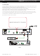
3.6 PRACTICAL LOOPS
The loop cable can be gure 8 cable, copper foil or multi-wire as long as the resistance is compatible with the amplier
requirements (preferred load resistance range is 0.2Ω to 1.7Ω). That includes feeder cable from amplier location, all
terminations and the loop itself. In the simplest installation, the loop is terminated at the amplier.
The g 8 cables can be bulky under carpet utilising thinner underlay and other oor covering. Foil and ribbon has a very
low prole under carpet but are more prone to damage from excessive localised force or uneven ooring which moves
with loading.
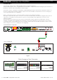
•Figure 8 cable (Note Flexibility: Resistance per cable length can be halved by paralleling or used as 2 Turn Cable)
Description Max Current /
leg
Resistance/100m Uses
W2119 7.5A 2.45Ω Small-medium loops
W2135 10A 1.85Ω Larger loops
W4052 Heavy Duty 17A 1.05Ω Larger loops/feeder cable
W4154 Very HD (Feeder) 20A 0.45Ω HD Feeder cable only
•Multi-wire ribbon
Description
W2616 16 wires 28AWG=1.296mm²
3.7 STEPS IN LOOP DESIGN (a suggested approach)
1. Decide location and measure loop size (length x width plus distance to Loop Drive Amplier).
2. Check environmental (background) magnetic noise level (A-weighted) using Field Strength meter (FSM). This will
be a combination of 50Hz Hum associated with proximity of mains cabling or switchboards and 100Hz Buzz
caused by rectication or light dimmers.
3. Adjust location if required after noise level checks, any identied thoroughfares through the space and other
factors affecting the space.
4. Calculate average current in single turn to give 100A/m eld strength, from i = a ÷ 9
5. Determine loop wire resistance (R) compatible with amplier requirements
6. Determine amplier drive characteristics to meet loop drive requirements
7. If possible, install/tape temporary loop into place on oor
8. Inject 1kHz tone into amplier, adjust gain control to correct operating level (setting current for long term average
Field Strength of 100mA/m.)
9. Conrm Frequency Response of system tone 100Hz and 5kHz at +/-3dB (unweighted)
10. Verify signal quality with FS at 400mA/m (approximate) Note: correct signal should be a pulsed tone
11. For reference and repeatable calibrations, manually plot long term FS readings in selected reference locations.
12. Fit appropriate signage for system compliance under BCA.
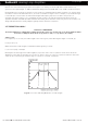
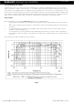
As a starting point for typical Perimeter loops, the long term average current is approximately the length of the shorter
side divided by 9 and the max (short term) current is 12dB higher i.e. approx. 4 times the length of shortest side divided by
9.
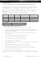
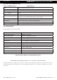
Loop Design
Loop Resistance and Cable Choice: (as to be used with A4210 and A4212 ampli�ers) Loop Cable Types:
The table shown below provides examples of Redbacks’ cables which would be suitable.
Cat No:
Cat No: