
Tus neeg siv phau ntawv

www.redbackaudio.com.au
Redback® Proudly Made In Australia12
Redback® Hearing Loop Ampliers
Background Noise:
Measure the environmental background electromagnetic noise utilising a Field Strength Meter (FSM) with the loop
system off. The required gure is -32dB (re 400mA/m) ideally preferred if 47dB! Will accept -22dB as useable but report.
Hearing induction loop systems for large oor areas need to be carefully designed. Simple ‘perimeter loop’ layouts which
work well for small rooms with timber oors, are often not suitable for larger rooms. For example, loops installed in large
rooms built upon concrete slabs can suffer eld strength and frequency response losses due to the presence of
structural steel reinforcement (or ‘reo’) laid within the slab. In order to provide an installed system which meets the
applicable Australian Standards (AS1428 and AS60118.4-2007) greater attention needs to be given to the site data, loop
design and implementation. Finally adequate signage must be utilised for compliance.
3.5 THEORETICAL LOOPS
Denition of AMP/METRE:
A eld strength (FS) of 1 Amp/metre (1A/m) exists at the centre of a circular loop of one metre diameter when
a current of 1 Amp rms ows in the loop. (from H = I/2R, I = loop current, R = radius)
Square Loops:
For a square loop of one turn, the eld strength at the centre is given, with “a” being the length of each side, by:
H = (2√2 / π) x (i / a)
Which means that a eld strength of 100mA/m would be given by a current:
i = (0.1 x π x a)/ 2√2 = a/9 amps
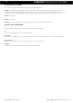
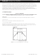
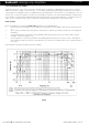
Naturally this calculation gives the eld strength (FS) only at the centre of the loop but we need to know about the
distribution of the eld over the whole area of the loop. Refer to the cross section of loop below and notice that at the
centre the FS is lower than just inside the edge of loop wire on each side of perimeter.
Fig 3.0 Cross section indicating Distribution of eld strength
Loop Design