
Tus neeg siv phau ntawv

www.redbackaudio.com.au
Redback® Proudly Made In Australia 11
Redback® Hearing Loop Ampliers
5. “Electric Grill” variation of the Perimeter Loop: Fitted as continuous sections approx. 2m wide giving a more
consistent eld and lowering spill and improved metal loss performance. Uses substantially more cable, requires
considerations regarding lower resistance cable and potential for cable damage if tted under oor cladding in
heavy trafc area.
6. Cancellation Loop (Passive): In the simplest form, a narrow loop added to a Perimeter Loop, laid as a
“g 8”end of the main loop. The design of the extra loop is critical and best tted by trial and error.
7. Ultra Low Spill Array: With mathematical Simulation and extremely precise placement of loop components
(down to <50mm) an Ultra-Low Spill System can be achieved with spill down to approx. 1m. A site visit for sample
test measurements (data) would enhance the quality of results.
3.4 THE AMPLIFIER
The preferred amplier design must incorporate a compressor for reduction of the dynamic range and a limiter to protect
the amplier output from clipping (esp at high frequencies) and thus eliminating any risk of generating EMC transmissions
i.e. must comply with C-tick requirements. It is also preferred that the amplier has a true current drive output and thus
minimizing problems with low impedance and driving an inductive load. Plan for the amplier to have 20% margin.
[The amplier must be capable of short term delivery of pulsed tone (125mS bursts) of current to achieve 400mA/m with
no distortion see extract from AS 60118.4-2007]
Please Note: The amplier’s maximum coverage area is measured in a free eld situation. In reality (with metallic objects,
like reinforced concrete) the coverage could be reduced by approximately 20-50%.
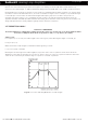
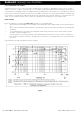
Extract from AS60118.4 (2007)
In practical terms, the recommended eld strength, based on Australian Standard 60188.4 (2007):
100mAmps/metre long term average (>60 secs) i.e. -12dB ref 400mA/m (rms)
400mAmps/metre (0.125secs) becomes 0dB ref and THD less than 1%.
Background noise -32dB A-weighted ref 400mA/m
Please note that this standard is about the ability of the amplier to deliver correct current into loop.
The aim of AFILs is to obtain:
Reasonable magnetic eld strength within the working area at ear level (1.2 metre sitting, 1.6 metre standing), per
AS60188.4.
Minimal overspill which could cause interference with other similar systems or compromise condentiality
Acceptably uniform magnetic eld strength over frequency range 100Hz to 5000Hz, as per AS60188.4. Signal
processing to achieve compression/limiting so that the variation in output level is limited in Dynamic Range and to ensure
that the amplier never goes into clipping (severe distortion) thus creating unwanted EMC interference.
Metal:
The presence of metal within the fabric/structure of buildings has an impact on loop performance. When any magnetic
eld generated, (by the audio loop in this case), Eddy currents are generated as a result within any metal structures
within the space. The induced currents will lower the main magnetic eld in localized spots/areas causing degradation to
the audio signal level or modications to the tonal balance resulting in lack of clarity at especially at higher frequencies.
The type of metal and the prole has a bearing on amount of loss. Examples of metallic structures include concrete oor
reinforcement, suspended ceilings, metal counters and lifts.
By careful attention to design and detail, the effects of metal can be minimised and sometimes completely eliminated.
“Magnetic Field Strength in Audio-Frequency Induction Loops for Hearing Aid Purposes”: The rigorous standard for Au-
dio Induction Loop Systems, making Australia internationally compliant in regard to eld strength and audio quality for
the hearing impaired. This denes the performance criteria of an induction loop system. The key elements may be
summarised:
• Field Strength in the specied listening area shall be -20dB re 1A/m average i.e. 100mA/metre long term aver-
age, using a 1kHz sinusoidal input, with a variation of +/-3dB.
• short term peaks up to 400mAmps/metre (0.125secs integration time)
• Environmental Magnetic Background noise shall be no higher than -40dB A-weighted (measured with the loop
system off).
• Frequency Response of the system shall be from 100Hz to 5000Hz. The variation should be no more than +/-
3dB from the value taken at 1kHz.
The international standard is IEC 60118.4 (also known as SN, EN or BS 60118.4)
Loop Design