
Tus neeg siv phau ntawv

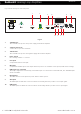

www.redbackaudio.com.au
Redback® Proudly Made In Australia10
Redback® Hearing Loop Ampliers
3.0 LOOP DESIGN
3.1 LOOP DESIGN GUIDELINES
Note: The most successful loops are designed with access to the site for measurements and proof of concept prior to
completion of facility. In the case of an existing venues, access limitations may lead to compromise in nal performance.
In brief, Assisted listening Systems (ALS) include AM/FM Transmitters/Receivers, Infrared Transmitters/Receivers and
Induction Loop Systems. Most Hearing Aid Devices are available with the built-in Telecoil (T) option. No additional
equipment is required for the pickup of the Electro Magnetic signal therefore making them a versatile device for detecting
an electronic signal.
In Audio Frequency Induction Loops (AFILs), the signal is baseband audio and requires only a simple Telecoil pickup
(Hearing Aid tted with T-coil). Listening (area) can be controlled by the loop layout and the system is not interrupted by
physical obstacles. On the down side the signal can be affected by mains borne interference, spill from adjacent loops and
variations of frequency response due to metal loss or localised variations in magnetic eld strength. In Australia AFILs are
the most commonly deployed hearing assistance mechanisms.
Loop locations: Apart from public spaces as set down by the BCA, loops can be utilized in lifts, trains, taxis, domestic
locations (e.g. Living/lounge rooms), etc.
[These specications relate to the vertical component of the magnetic eld. The T-coil in hearing aids is
usually mounted vertically. Not all hearing aids comply with this standard which often causes complaints
about loop systems. Exceptions must be made in certain situations where the head of the listener is not
vertical (places of worship, hospitals and recovery areas as people may be kneel, prone or supine).]
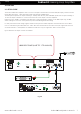
3.2 THE LOOP
In its simplest form, is a copper conductor tted to the perimeter of area in interest (g 8 cable is very satisfactory). As
the installation gets more demanding due to metal loss (e.g. extensive use of reinforcement steel) and requirements for
tight control of spill, the loop design becomes more complicated including use of multiple ampliers. For such applications
requiring low spill, high metal loss compensation designs, it is recommended that a consulting engineer with appropriate
experience be utilised. The A 4210/12 ampliers are not intended for use in multiple amplier designs.
See “Loop Resistance” and cable choice under Practical Loop section for more information.
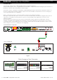
3.3 LOOP TYPES
1. Counter Loops: Loops tted to service/information counters e.g. Post Ofce, Doctors reception area, Rail Ticket
ofce, etc. Can be a simple matt style pre-manufactured unit or more effectively a combination vertical/horizontal
coil xture under the counter/desk structure of the facility driven by a small amplier and microphone
combination.
2. Perimeter Loop: Placing a loop typically at the edge (or 600mm in) of room boundary with a suitable feed
termination from amplier. The loop wire resistance including feeder cable must meet requirements of amplier
specications. Some problems may arise regarding metal loss and loop spill into adjacent areas. Never install the
loop cable at head (Hear Aid) height as performance can be erratic due to eld strength variation. Spill can be as
far as 3.5 times width of loop, (rolling off then decaying to complete zero). Avoid installation of single Perimeter
Loops in spaces larger than 10m x 10m, as the eld strength will potentially have large variations. Plan for 2 or
multiple loops.
3. 2-Turn Perimeter Loop: A variation of the Perimeter loop is a 2-turn cable loop, which increases the eld
strength by 6dB, however the loop impedance goes up (4 times) and increases the risk of the amplier clipping
especially at high frequencies.
4. Single Array Loop: Two or multiple “g 8” type segments nominally 2 to 5m, preferably all the same width.
Requires less current than a Perimeter loop (3dB per 2 sections) but exhibits a brief but sharp signal “Null” at each
segment or cable crossover. Most suitable for a permanent seating areas and individual desks (Classroom setup).
Has limitations as the number of loop segments due to metal loss increases.
Loop Design
Redback does not guarantee absolute outcomes from following any speci�c information produced in these
instructions. This is purely a guide and assumes the Loop Design is made by someone with the appropriate
quali�cations or experience.
As for the loop resistance, A4210 and A4212 Hearing Loop Ampli�ers preferred load resistance range is 0.2Ω to 1.7Ω
(inherently short circuit proof and stability guaranteed to 2Ω).