Redback® Hearing Loop Amplifiers Operating Manual A 4210 80VA Hearing Induction Loop Amplifier A 4212 280VA Hearing Induction Loop Amplifier SUITABLE FOR SIMPLE ONE AMPLIFIER DESIGNS. NOT DESIGNED FOR COMPLEX MULTIPLE AMPLIFIER SYSTEMS. NOT SUITABLE FOR INSTALLS WITH ADJACENT SYSTEMS. User manual revision number: 1.1 22/09/2020 IMPORTANT NOTE: Please read these instructions carefully from front to back prior to installation. They include important setup instructions.
Redback® Hearing Loop Amplifiers Since 1976 Redback ampli�ers have been manufactured in Perth, Western Australia. With over 40 years experience in the commercial audio industry, we offer consultants, installers and end users reliable products of high build quality with local product support.
Contents Redback® Hearing Loop Amplifiers 1.0 Overview 1.1 Introduction 1.2 Features 1.3 What’s in the box 1.4 Front panel guide 1.5 Rear panel connections 4 4 4 5 6 2.0 Setup 2.1 Setup Guide 2.2 EWIS Input 2.3 DIP Switch Settings 2.4 LED status indicators 7 8 9 9 3.0 Loop Design 3.1 Loop Design Guidelines 3.2 The Loop 3.3 Loop Types 3.4 The Amplifier 3.5 Theoretical Loops 3.6 Practical Loops 3.7 Steps In Loop Design 3.8 Placement of Loops 10 10 10 11 12 13 13 14 4.0 Terms and Abbreviations 15 5.
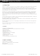
Redback® Hearing Loop Amplifiers Overview 1.0 OVERVIEW 1.1 INTRODUCTION Induction Loop amplifiers, also known as T-loop or Hearing Loop amplifiers, are installed to greatly enhance the listening experience of people using hearing aids. The hearing loop, as its name suggests, is basically a loop of wire which surrounds a designated area to transmit audio to a hearing aid.
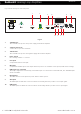
Redback® Hearing Loop Amplifiers Overview 1.4 FRONT PANEL GUIDE Fig 1.4 shows the layout of the front panel. 1 2 3 4 5 6 80VA Hearing Loop Amplifier Model : A 4210 Mic Vol 4 Line Vol 6 4 6 4 Power Master Aux Vol 6 4 6 0 10 Signal Present 8 2 0 10 8 2 0 10 8 2 0 10 -15dB -9dB -6dB -3dB 0dB Overtemp On 8 7 8 2 Alert/Evac Level 10 9 Fig 1.4 1 Mic volume control Use this control to adjust the microphone volume.
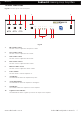
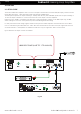
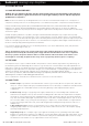
Overview Redback® Hearing Loop Amplifiers 1.5 REAR PANEL CONNECTIONS Fig 1.5 shows the layout of the rear panel. 1 2 3 4 5 SW 1 CAUTION RISK OF ELECTRIC SHOCK OPEN BY QUALIFIED PERSONNEL ONLY ! Made in Australia by Altronic Distributors Pty Ltd +24V DC FUSE DIP Switch Options On Off Vox enabled Vox disabled Not Used 2 3 Not Used 4 Phantom Power On Phantom Power Off OUTPUT www.altronics.com.au 6 L L R R PHASE SHIFT -24V DC FUSE DIP Vox Switches Sens.
Redback® Hearing Loop Amplifiers Setup 2.0 SETUP 2.1 SETUP GUIDE The A 4210 and A 4212 amplifiers have a total of four inputs. A balanced 3 Pin female XLR (Mic input), a balanced 3 Pin female XLR (Line input), a dual RCA (Aux input) and a dual RCA (EWIS input). The Microphone input has an input sensitivity of 100mV, while the Line, Aux and EWIS inputs have an input sensitivity of 1V. The Line input is suitable for connection from the Line Level output of another amplifier.
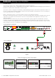
Setup Redback® Hearing Loop Amplifiers 2.2 EWIS INPUT The A 4210/12 amplifiers have a dedicated EWIS input for emergency situations. A Fire Evacuation System can be con�gured when the A 4210/12 is complemented with an Emergency Tone Generator or Evacuation Controller such as the A 4565 as shown in Fig 2.1. The A 4565 controller is designed around industry standard building emergency alert/evacuate requirements.
Setup Redback® Hearing Loop Amplifiers 2.3 DIP SWITCH SETTINGS These switches configure the phantom power and Vox triggering function. Switch 1 - Enables the VOX Triggering. The VOX is activated when a signal is applied to the EWIS input. The VOX sensitivity of the EWIS input is adjusted via the (Alert/Evac Level) trimpot adjustment on the front panel. Once the VOX is activated the Mic, Line and AUX inputs will be overridden, and the audio from the EWIS input will be output.
Redback® Hearing Loop Amplifiers Loop Design 3.0 LOOP DESIGN 3.1 LOOP DESIGN GUIDELINES Redback does not guarantee absolute outcomes from following any speci�c information produced in these instructions. This is purely a guide and assumes the Loop Design is made by someone with the appropriate quali�cations or experience. Note: The most successful loops are designed with access to the site for measurements and proof of concept prior to completion of facility.
Loop Design Redback® Hearing Loop Amplifiers 5. “Electric Grill” variation of the Perimeter Loop: Fitted as continuous sections approx. 2m wide giving a more consistent field and lowering spill and improved metal loss performance. Uses substantially more cable, requires considerations regarding lower resistance cable and potential for cable damage if fitted under floor cladding in heavy traffic area. 6.
Redback® Hearing Loop Amplifiers Loop Design Background Noise: Measure the environmental background electromagnetic noise utilising a Field Strength Meter (FSM) with the loop system off. The required figure is -32dB (re 400mA/m) ideally preferred if 47dB! Will accept -22dB as useable but report. Hearing induction loop systems for large floor areas need to be carefully designed. Simple ‘perimeter loop’ layouts which work well for small rooms with timber floors, are often not suitable for larger rooms.
Redback® Hearing Loop Amplifiers Loop Design 3.6 PRACTICAL LOOPS Loop Resistance and Cable Choice: (as to be used with A4210 and A4212 ampli�ers) Loop Cable Types: The loop cable can be figure 8 cable, copper foil or multi-wire as long as the resistance is compatible with the amplifier requirements (preferred load resistance range is 0.2Ω to 1.7Ω). That includes feeder cable from amplifier location, all terminations and the loop itself.
Redback® Hearing Loop Amplifiers Loop Design 3.8 PLACEMENT OF LOOPS Optimum position for loop is at floor level (up to 250mm above) or under floor depending on access to floor covering and floor structures or 2.4m to 3.5m above floor i.e. in suitable ceiling. (Bearing in mind the working area at ear level i.e. 1.2m sitting, 1.
Redback® Hearing Loop Amplifiers Specifications 4.0 TERMS AND ABBREVIATIONS Terms and Abbreviations AFILs FS FSM T (“T” setting) mA/m 0.125secs integration time dB L A-weighted rms Spill Explanations Audio Frequency Induction Loops Field Strength (Magnetic) Calibrated Meter to indicate magnetic Field Strength (Baseband Audio) Telecoil (H) Magnetic Field strength measured in milliAmperes per metre An extended processing time measurement for level meter (not readily available but normal PPM reads approx.