
User Manual


E-M-HF8-V2_10
Rotronic AG
Bassersdorf, Switzerland
Document code Unit
HygroFlex HF8 Humidity Temperature
Transmitter: User Guide
Instruction Manual
Document Type
Page
4 of 35
Document title
© 2012; Rotronic AG E-M-HF8-V2_10
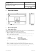
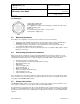
2 Dimensional drawings
Dimensions in mm
3 General description
3.1 Power supply options
The HF8 can be ordered with different power supply options. Please verify the product identification label to
determine which power supply option is installed on your transmitter.
a) Option 1: 15 to 40 VDC or 12 to 28 VAC – 50/60 Hz, direct connection
With this option, the negative (or ground) side of the analog output signals is tied to the negative side
(VDC) or neutral (VAC) of the power supply .
Depending on the type of output signal, the HF8 will operate with the following minimum voltage
0…1 V outputs: 5 VDC or 5 VAC
0…5 V outputs: 10 VDC or 8 VAC
0…20 mA or 4 …20 mA outputs: 6 VDC or 5 VAC with 0 Ω load
15 VDC or 12 VAC with 500 Ω load
Typical maximum current consumption:
b) Option 2: 9 to 36 VDC or 7 to 24 VAC – 50/60 Hz, galvanically isolated
With this option the HF8 is equipped with an internal power module that provides galvanic isolation
between power and the analog signals. As a result, the negative (or ground) side of the analog output
signals is not tied with the negative side (VDC) or neutral (VAC) of the power supply.