
User Manual


E-M-HF8-V2_10
Rotronic AG
Bassersdorf, Switzerland
Document code Unit
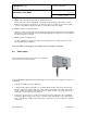
HygroFlex HF8 Humidity Temperature
Transmitter: User Guide
Instruction Manual
Document Type
Page
2 of 35
Document title
© 2012; Rotronic AG E-M-HF8-V2_10
Table of contents
1
Overview .............................................................................................................................................. 3
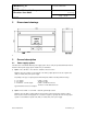
2 Dimensional drawings ........................................................................................................................ 4
3 General description ............................................................................................................................. 4
3.1 Power supply options ....................................................................................................................... 4
3.2 Probe inputs ..................................................................................................................................... 5
3.3 Measured parameters ...................................................................................................................... 6
3.4 Calculated psychrometric parameters .............................................................................................. 6
3.5 Custom Calculations ......................................................................................................................... 6
3.6 Real time clock ................................................................................................................................. 7
3.7 Data logging function ........................................................................................................................ 7
3.8 Analog outputs, relay contacts and digital interface options ............................................................. 7
3.9 Optional display and keypad............................................................................................................. 8
3.10 Audible alarm (beeper) ..................................................................................................................... 9
3.11 Service connector ............................................................................................................................. 9
3.12 Protection grade of models with Ethernet interface .......................................................................... 9
3.13 HW4 Software compatibility ............................................................................................................ 10
4 User configurable settings and functions ....................................................................................... 10
4.1 Function overview (HF8 and HygroClip 2 probe) ............................................................................ 10
4.2 Interaction between the HF8 and HygroClip 2 probe functions ...................................................... 11
4.3 Configuration of the analog output signal type ............................................................................... 12
5 Mechanical installation ..................................................................................................................... 12
5.1 General guidelines .......................................................................................................................... 12
5.2 HF8 enclosure ................................................................................................................................ 13
5.3 Installation of the enclosure and probe ........................................................................................... 13
6 Electrical installation ........................................................................................................................ 14
6.1 General wiring guidelines ............................................................................................................... 14
6.2 Guidelines for RS-485 wiring .......................................................................................................... 15
6.3 Cable grip and cable specifications ................................................................................................ 15
6.4 Wiring ............................................................................................................................................. 15
7 Operation ........................................................................................................................................... 20
7.1 Analog outputs ................................................................................................................................ 20
7.2 Digital interface ............................................................................................................................... 20
7.3 Optional display and keypad........................................................................................................... 21
7.4 Frequently used settings ................................................................................................................ 25
7.5 Data logging function ...................................................................................................................... 26
7.6 Relay contacts ................................................................................................................................ 27
7.7 Audible alarm (beeper) ................................................................................................................... 27
8 Maintenance....................................................................................................................................... 27
8.1 Service cable .................................................................................................................................. 27
8.2 Location of the service connector (mini USB type) ......................................................................... 27
8.3 Periodic calibration check of the HygroClip 2 probe ....................................................................... 28
8.4 HF8 probe calibration and adjustment procedures ......................................................................... 28
8.5 Cleaning or replacing the probe dust filter ...................................................................................... 29
8.6 Validation of the output signals transmission .................................................................................. 30
9 Firmware updates .............................................................................................................................. 30
10 Technical data ................................................................................................................................... 31
10.1 Specifications ................................................................................................................................. 31
10.2 Dew point accuracy ........................................................................................................................ 34
11 Accessories ....................................................................................................................................... 34
12 Supporting documents ..................................................................................................................... 35
13 Document releases ........................................................................................................................... 35