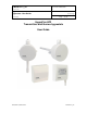
E-M-HF3-V1_22 Rotronic AG Bassersdorf, Switzerland Document code Unit HygroFlex HF3 Transmitters and Thermohygrostats: User Guide Instruction Manual Document Type Page Document title 1 of 27 HygroFlex HF3 Transmitters and thermo-hygrostats User Guide © 2009-2011; Rotronic AG E-M-HF3-V1_22
E-M-HF3-V1_22 Rotronic AG Bassersdorf, Switzerland Document code Unit HygroFlex HF3 Transmitters and Thermohygrostats: User Guide Document title Instruction Manual Document Type Page 2 of 27 Table of contents 1 2 2.1 3 3.1 3.2 3.3 3.4 3.5 3.6 3.7 4 4.1 4.2 5 5.1 5.2 5.3 5.4 6 6.1 6.2 6.3 7 7.1 7.2 8 8.1 8.2 8.3 8.4 9 10 10.1 10.2 11 12 13 Overview ...............................................................................................................................................
E-M-HF3-V1_22 Rotronic AG Bassersdorf, Switzerland Document code Unit HygroFlex HF3 Transmitters and Thermohygrostats: User Guide Document title Instruction Manual Document Type Page 3 of 27 Applicability: This manual applies to all instruments of the HF3 series with firmware version 1.x, where 1.x can be 1.0, 1.1, etc. Changes to the last digit of the version number reflect minor firmware changes that do not affect the manner in which the instrument should be operated.
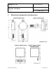
E-M-HF3-V1_22 Rotronic AG Bassersdorf, Switzerland Document code Unit HygroFlex HF3 Transmitters and Thermohygrostats: User Guide Document title 2 Instruction Manual Document Type Page 4 of 27 Mechanical configurations and dimensions © 2009-2011; Rotronic AG E-M-HF3-V1_22
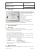
E-M-HF3-V1_22 Rotronic AG Bassersdorf, Switzerland Document code Unit HygroFlex HF3 Transmitters and Thermohygrostats: User Guide Instruction Manual Document Type Page Document title 2.1 5 of 27 Display option The LC display option is available only with type R and type S mechanical configurations. The upper line of the display corresponds to relative humidity or dew / frost point and the bottom line corresponds to temperature.
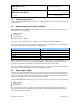
E-M-HF3-V1_22 Rotronic AG Bassersdorf, Switzerland Document code Unit HygroFlex HF3 Transmitters and Thermohygrostats: User Guide Document Type Page Document title 3.3 Instruction Manual 6 of 27 Calculated parameters Using the ROTRONIC HW4 software, the HF3 can be configured by the user to calculate either the dew point or the frost point. 3.
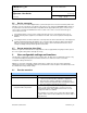
E-M-HF3-V1_22 Rotronic AG Bassersdorf, Switzerland Document code Unit HygroFlex HF3 Transmitters and Thermohygrostats: User Guide Document Type Page Document title 3.6 Instruction Manual 7 of 27 Service connector The service connector is a UART digital interface (Universal Asynchronous Receiver Transmitter) with a miniUSB type connector.
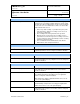
E-M-HF3-V1_22 Rotronic AG Bassersdorf, Switzerland Document code Unit HygroFlex HF3 Transmitters and Thermohygrostats: User Guide Instruction Manual Document Type Page Document title 8 of 27 MEASUREMENT ACCURACY AND RELIABILITY ► Data recording The data recording function differs from a true data logging function in the sense that the AirChip 3000 does not time stamp the data.
E-M-HF3-V1_22 Rotronic AG Bassersdorf, Switzerland Document code Unit HygroFlex HF3 Transmitters and Thermohygrostats: User Guide Instruction Manual Document Type Page Document title 4.2 9 of 27 Factory default settings Note: Configuration of the HF3 by the user and access to its functions requires a PC with the ROTRONIC HW4 software (version 2.1.1 or higher) installed.
E-M-HF3-V1_22 Rotronic AG Bassersdorf, Switzerland Document code Unit HygroFlex HF3 Transmitters and Thermohygrostats: User Guide Instruction Manual Document Type Page Document title 5 Mechanical installation 5.1 General guidelines 10 of 27 Relative humidity is extremely dependent on temperature. Proper measurement of relative humidity requires that the probe and its sensors be at exactly the temperature of the environment to be measured.
E-M-HF3-V1_22 Rotronic AG Bassersdorf, Switzerland Document code Unit HygroFlex HF3 Transmitters and Thermohygrostats: User Guide Document title 5.4 Instruction Manual Document Type Page 11 of 27 Type R and S – surface mount Type R and type S consist of a base plate and an electronics module that plugs into the base plate. The base plate is installed and wired first. The base plate should be installed with terminals 1 to 4 placed on top. Preferably, use a cable with 18 AWG wires.
E-M-HF3-V1_22 Rotronic AG Bassersdorf, Switzerland Document code Unit HygroFlex HF3 Transmitters and Thermohygrostats: User Guide Electrical installation 6.1 General guidelines Document Type Page Document title 6 Instruction Manual 12 of 27 Power supply wiring Heavy machinery and instrumentation should not share the same power supply wiring. If this cannot be avoided, noise filters and surge protectors should be used. Most UPS devices have those features already integrated.
E-M-HF3-V1_22 Rotronic AG Bassersdorf, Switzerland Document code Unit HygroFlex HF3 Transmitters and Thermohygrostats: User Guide Document title Instruction Manual Document Type Page 13 of 27 Lightning protection Cabling in areas with a risk of lightning requires a lightning protection. For cabling underground in between buildings, we recommend the use of special fiber optic cables. If this is not possible, use copper cables that are suitable for underground installation. 6.
E-M-HF3-V1_22 Rotronic AG Bassersdorf, Switzerland Document code Unit HygroFlex HF3 Transmitters and Thermohygrostats: User Guide Instruction Manual Document Type Page Document title 14 of 27 Terminal block diagram for type D and W Terminals Description T-OUT Temperature output (+) OUT-2 V+ Power supply: 10…28 VDC (+) H-OUT Relative humidity or dew point (+) OUT-1 V+ Power supply: 10…28 VDC (+) Note: connect the + of the power supply to only one of the V+ terminals.
E-M-HF3-V1_22 Rotronic AG Bassersdorf, Switzerland Document code Unit HygroFlex HF3 Transmitters and Thermohygrostats: User Guide Instruction Manual Document Type Page Document title 15 of 27 6.3.2 HF33: 3-wire transmitter Electrical diagram for voltage outputs The maximum permissible cable length can be determined under consideration of the voltage drop caused by the current flowing to the devices connected to the unit.
E-M-HF3-V1_22 Rotronic AG Bassersdorf, Switzerland Document code Unit HygroFlex HF3 Transmitters and Thermohygrostats: User Guide Instruction Manual Document Type Page Document title 16 of 27 Terminal block diagram for type R and S Terminals Description 1 Power supply: 15…40 VDC (+) or 12…28 VAC (Phase) 2 Power supply (-) or neutral / ground 3 Relative humidity or dew point (+) OUT-1 4 Temperature output (+) OUT-2 5 Not used 6 Not used Measuring humidity or temperature only Operation
E-M-HF3-V1_22 Rotronic AG Bassersdorf, Switzerland Document code Unit HygroFlex HF3 Transmitters and Thermohygrostats: User Guide Instruction Manual Document Type Page Document title 17 of 27 Terminal block diagram for type D and W L1 L2 P1 P2 Terminals Description K1-1 Power supply: 15…40 VDC (+) or 12…28 VAC (Phase) K1-2 Power supply (-) or neutral / ground K2-1 Relay 1: humidity. Normally closed K2-2 Relay 1: humidity. Common K2-3 Relay 1: humidity.
E-M-HF3-V1_22 Rotronic AG Bassersdorf, Switzerland Document code Unit HygroFlex HF3 Transmitters and Thermohygrostats: User Guide Instruction Manual Document Type Page Document title 18 of 27 7 Operation 7.
E-M-HF3-V1_22 Rotronic AG Bassersdorf, Switzerland Document code Unit HygroFlex HF3 Transmitters and Thermohygrostats: User Guide Document Type Page Document title 7.2 Instruction Manual 19 of 27 HF34 thermo-hygrostat 7.2.
E-M-HF3-V1_22 Rotronic AG Bassersdorf, Switzerland Document code Unit HygroFlex HF3 Transmitters and Thermohygrostats: User Guide Document title Instruction Manual Document Type Page 20 of 27 Procedure 1: 1) Use the appropriate model of service cable (see Maintenance > Service Cable) to connect the HF34 2) 3) 4) 5) 6) service connector to a USB port of a PC with the HW4 software installed.
E-M-HF3-V1_22 Rotronic AG Bassersdorf, Switzerland Document code Unit HygroFlex HF3 Transmitters and Thermohygrostats: User Guide Instruction Manual Document Type Page Document title 8 Maintenance 8.1 Service cable 21 of 27 IMPORTANT: o Use service cable AC3009 with all 2-wire, loop powered transmitters. This cable powers up the transmitter via the service connector.
E-M-HF3-V1_22 Rotronic AG Bassersdorf, Switzerland Document code Unit HygroFlex HF3 Transmitters and Thermohygrostats: User Guide Document title 8.3 Instruction Manual Document Type Page 22 of 27 Periodic calibration check Both the Pt 100 RTD temperature sensor and associated electronics are very stable and should not require any calibration after the initial factory adjustment. Long term stability of the ROTRONIC Hygromer humidity sensor is typically better than 1 %RH per year.
E-M-HF3-V1_22 Rotronic AG Bassersdorf, Switzerland Document code Unit HygroFlex HF3 Transmitters and Thermohygrostats: User Guide Instruction Manual Document Type Page Document title 10 Technical data 10.1 Specifications General HF32 Device type Humidity temperature transmitter Circuit type 2-wire, loop powered Mechanical configuration types D, R, S and W Power supply and connections HF32 HF33 Supply voltage (VDD) 10…28VDC V min = 10 V + (0.02 x Load*) *Load resistance in ohms.
E-M-HF3-V1_22 Rotronic AG Bassersdorf, Switzerland Document code Unit HygroFlex HF3 Transmitters and Thermohygrostats: User Guide Instruction Manual Document Type Page Document title Configurable analog outputs HF32 Output 1 Can be made to correspond to any parameter HF33 Factory default parameter Relative humidity or dew / frost point Factory default scale 0…100 %RH or -50…50 °C DP or -50…100 °F DP Output 2 24 of 27 Can be made to correspond to any parameter Factory default parameter T
E-M-HF3-V1_22 Rotronic AG Bassersdorf, Switzerland Document code Unit HygroFlex HF3 Transmitters and Thermohygrostats: User Guide Instruction Manual Document Type Page Document title 25 of 27 General specifications HF32 HF33 Optional display (S and R configurations only) LC, 1 or 2 decimals resolution, no backlight, trend indication LC, 1 or 2 decimals resolution, with backlight and trend indication Probe material Polycarbonate, except type R and S Polycarbonate Probe dust filter material
E-M-HF3-V1_22 Rotronic AG Bassersdorf, Switzerland Document code Unit HygroFlex HF3 Transmitters and Thermohygrostats: User Guide Document title 10.2 Instruction Manual Document Type Page 26 of 27 Dew point accuracy The HF3 can be configured to calculate either the dew point or frost point based on the measurement of relative humidity and temperature.
E-M-HF3-V1_22 Rotronic AG Bassersdorf, Switzerland Document code Unit HygroFlex HF3 Transmitters and Thermohygrostats: User Guide Document Type Page Document title 11 Instruction Manual 27 of 27 Accessories For accessories and parts such as the HW4 configuration software, service cables, calibration accessories and spare dust filters, please see document E-M-HC2-accessories 12 Supporting documents Document File Name Contents E-M-HC2-accessories Accessories and parts for probes, indicators