
User Guide
7
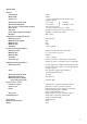
Zero adjustment
NOTE: After making any zero adjustment to instruments fitted with control or alarm contacts the relay operating
point must be checked and adjusted as described on page 10.
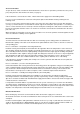
Zero adjustment – temperature recorders and wet and dry bulb humidity instruments:
All instruments are calibrated against a standard thermometer before despatch but should be checked in case of
slight disturbance during transit. Immerse a standard thermometer with the bulb and check the readings. If
adjustment is necessary open the door and rotate the small knurled screw S (in Fig. 3.) to bring the pen to the
correct reading.
Zero adjustment – pressure recorders:
Use a reliable pressure gauge to check the readings and
adjust, if necessary, as for the temperature recorder.
Zero adjustment – temperature and humidity recorders:
Check the temperature reading against a standard mercury-in-
glass thermometer and the humidity reading against a whirling
hygrometer using hygrometric tables to relate humidity to wet
and dry thermometer readings.
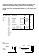
Hygrometric tables are compiled by the Meteorological Office
and obtainable from H.M. Stationery Office. Alternatively use
the Psychrometric tables by C.F. Marvin (issued by U.S.
Department of Commerce Weather Bureau) and obtainable
from C.F. Casella & Co. Ltd., Regent House, Brittania Walk,
London N.1.
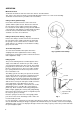
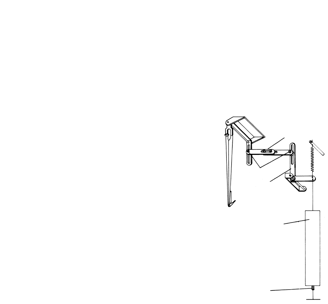
The zero setting may be adjusted using screw S (Fig. 3). If the
humidity reading requires more correction than that provided
by S, screw J, accessible through the bottom of the guard,
may be adjusted (Fig. 4).
In a bimetallic temperature measuring system the linkages and
zero adjustments are the same as for the hygroscopic
measuring system.
Start-up Check
Before putting the controller into operation make certain it is correctly installed and operational by checking that:
1. The pens operate freely, write cleanly on the chart and can pass each other without touching.
2. Measuring elements are correctly installed.
3. Measuring systems are indicating correctly. If not refer to Zero Adjustment, above.
4. On electrical controllers:
Relays are energised above or below set point as required. If they are not, see Changing the Control Action,
page 10.
5. If a mechanical clock is fitted check that it is wound up (see Mechanical Clock, page 6).
Start-up procedure
Be sure that all steps in the start-up check have been completed.
1. Switch on mains supply to recorder.
2. Position setting pointers on desired alarm/control values.
3. Switch on mains supply to external electric alarm/control systems.
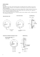
Fig. 4
Linearity adjustment
Ratio arm
Screw J
Hygroscopic
membrane
Pivots