
User Guide


15
FAULT FINDING
Recorder pen is inaccurate or gives no indication
1. Measuring element broken; capillary plugged or broken on temperature recorder.
Check elements or capillary and replace as necessary.
2. Disconnected linkage in recorder.
Re-connect or repair as necessary.
3. Recorder out of calibration, measuring element not damaged.
Check and calibrate if necessary, pages 11 and 12.
No record on chart
1. Pen not inking.
Fit new pen capsule, page 6.
2. Chart drive motor stopped.
Rewind, page 6. Replace if broken.
3. Chart clamp broken.
Replace by new assembly.
Poor Control – Electrical
1. Faulty relay.
Replace relay.
2. Friction in measuring system.
Correct action of measuring system.
3. Lack of electrical power in circuit being controlled.
Increase power rating of control equipment.
4. Power in circuit being controlled too high.
Decrease power rating of control equipment.
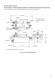
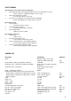
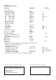
SPARES LIST
Description Part Number Reference
Chart Quote the number on the chart
supplied or duration and range. Fig. 1
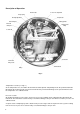
Chart clamp assembly (not programme controllers) 15321/608 Fig. 2(a)
Chart drive motor – electrical (assembled on moulding) Quote chart speed voltage and mains
frequency.
Chart drive motor – mechanical Quote chart speed and specify
“mechanical”.
Circlip – setting pointer spindle 600353
Electrical Control with spring contact on the Control Arm:
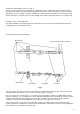
Spring contact assembly-relay energized below set point 15321 / 79 (min. type A) Fig. 7
Spring contact assembly-relay energized above set point 15321 / 80 (max. type C) Fig. 7
Striker contact pin 19 s.w.g. silver wire Figs. 5 & 7
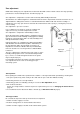
Hinge 15 / 240 Fig. 1
Hinge – pin 15 / 243
Hinge – screw 15 / 211
Hinge – spring 15 / 220
Key for lock FA 558
Lock with spring washer and catch 22656 / 142 Fig. 1
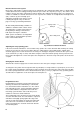
Pen arm – green (rear position) 15321 / 328 (stamped 8 on pen arm) Figs. 1 & 3
Pen arm – red (front position) 15321 / 327 (stamped 7 on pen arm) Figs. 1 & 3
Pen capsule – green P105M/0302 (pack of 5) Fig. 3
Pen capsule – red P105M/0301 (pack of 5) Fig. 3
Pen lifter 15 / 277