
User Guide

11
MAINTENANCE
Cutting a programme cam
The required programme should be drawn on to a spare recorder chart and transferred using carbon paper or a
similar method to the paper covering on the cam blank. Mark on this trace significant points of the programme
where the process state is important. Mark drilling centres on the radii of these programme points exactly 3mm
out from the points. Drill through with a 6mm drill. Join up the programme points using a saw, and smooth off the
profile between the points.
A cam cut in this way will only provide a programme which is an approximation to the requirement owing to
variations in the distance between the cam-follower and the pen at different positions on the chart. If required,
precise programme cams can be supplied to customers’ specifications.
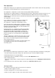
Fitting a new pen arm
Refer to the SPARES LIST, page 15 for the part numbers of the two pen arms. Make sure the correct replacement
arm (front or rear pen) is obtained. Follow the fitting instructions outlined under Inking System, page 6.
After fitting a new arm check the pen indication on the chart near the zero end of the range. See Zero Adjustment,
page 7.
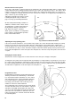
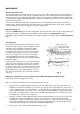
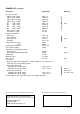
Pen Adjustment
The pen lifter must be below the arm before the clock is
started. If the pen is bent, the effective length of the pen
arm will be altered so that the pen will not record the
correct time at all temperatures. If when the chart is
stationary the time increases as the pen moves towards
the outside of the chart, the pen arm is too long, and
vice versa, see Fig. 9. The error can be corrected by
careful straightening of the pen or by bowing the pen
arm slightly. Adjust the pressure if necessary by bending
the hook Y in Fig. 3.
Instruments with more than one pen are adjusted in the
same way as those with only one. Each pen is adjusted
independently. The mounting for the pen arm closest to
the chart (the green pen) is reversed and the fibre tip nib
is shorter so that each pen can move freely across the
other’s path. Only the red pen will indicate the correct
time; the green pen being set to record 4mm in advance
of the red.
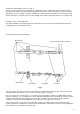
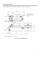
Calibration – Temperature or Pressure System; Wet and Dry Bulb Relative Humidity System
Switch off the electrical supply to the recorder.
Make sure all pivots and linkages are free moving and adjust as follows:
Allow recorder to stabilise with measuring element in a low temperature (or pressure) just above scale
minimum. Pen should record within ±1% of span of correct value. If necessary adjust zero screw S, Fig. 3.
If pen is significantly out of line with cockpiece, i.e. more than about 5 angular degrees, adjust screw S to
line up pen with cockpiece. Loosen the coarse zero adjustment screw holding the serrated compensator
carrier, Fig. 5. and adjust pen to record true value, making a fine adjustment on screw S after the coarse
zero adjustment screw has been re-tightened.
Allow the recorder to stabilise with measuring element in high temperature (or pressure) just under scale
maximum. Pen should record within ±1% of span of correct value. If not, adjust by moving the link
connecting the compensator arm to the ratio arm on the cockpiece, see Fig. 5. In order to move the link,
loosen the nut at the back of the ratio arm pivot. Raising the pivot will increase the pen movement and
lowering the pivot will reduce the movement. Re-tighten after adjustment.
Repeat steps 1 and 2 until no further adjustment is necessary.
1.
2.
3.
Fig. 9
Decrease length
Red pen arm too long
Red pen trace correct
Green pen trace correct
Red pen arm too short
Length of bow
Increase length