
User Guide
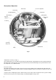
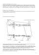
Electrical alarm/control system
Each relay is switched by a contact mounted on an arm linked to the setting pointer which makes or breaks with a
contact attached to the recording pen linkage when the pen reaches the set point (see Fig. 5.). The striker is fixed
relative to the pen arm and a spring loaded contact is fitted to the setting pointer linkage. One set of changeover
contacts is available for external connection for each set point. The contacts are usually labelled “normally closed”
(NC), “common” (C) and “normally open”
(NO) where normally means that no current
is flowing through the relay coil. Refer to
page 14 for any special wiring information.
On wet and dry bulb humidity controllers in
addition to standard control contacts for the
dry temperature a contact may be fitted on
the dry bulb pen linkage so that the wet
bulb depression may be controlled.
Alarm systems should have an independent
power supply to safeguard alarm operation
in the event of mains failure.
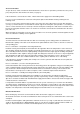
Adjusting the relay operating point
If the measured value indication is correct and the relay operates at a value other than that shown by the setting
pointer, the error may be corrected as follows. Move the setting pointer to the indicated value. Switch off the
electrical supply to the recorder and remove the chart, pens and upper chart plate. Slacken the two nylon screws
on the control unit (see Figs. 5 and 7) and slide it along the control arm until the sprung contact just touches the
fixed contact. Re-tighten the screws and replace the chart plate etc. Check the relay now operates at the desired
set point.
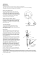
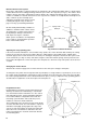
Changing the Control Action
Switch off the electrical supply to the recorder and remove the chart, pens and upper chart plate.
To change the relay action from energised below set point (E.B.) to energised above set point (E.A.) or vice-versa
the control unit incorporating the spring loaded contact should be unscrewed from the control arm and a unit with
the contact spring loaded in the reverse direction fitted in its place (see Fig. 7). Adjust the relay operating point as
described above. Tighten the screws and replace the chart plate etc.
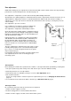
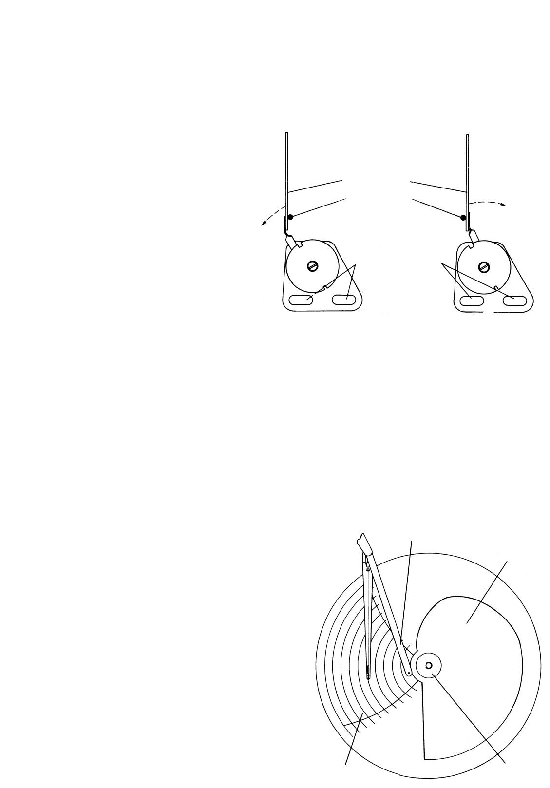
Programme Control
Programming is provided by a shaped transparent cam
driven by the chart motor and linked by a cam follower
to a control unit inside the instrument case. The control
unit continually operates external regulating equipment
in accordance with the configuration of the cam. The
measuring system monitors and records the process
variable as in the basic C105 instrument.
The programming cam is mounted over the chart directly
on to the chart drive shaft. The cam follower is a pivoted
arm with a roller lightly sprung against the edge of the
cam at one end and a linkage to the internal control unit
at the other. The cam follower is deflected as the cam
rotates and actuates the electrical control unit. All cams
are interchangeable.
10
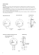
Fig. 7. Electrical Control Contacts
Fig. 8
Sprung contact
E.A.
E.B.
Striker pin
Slots for fixing screws
Part no. 15321–80
Cam follower
Programme cam
Cam clamp nut
Chart
Part no. 15321–79