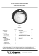
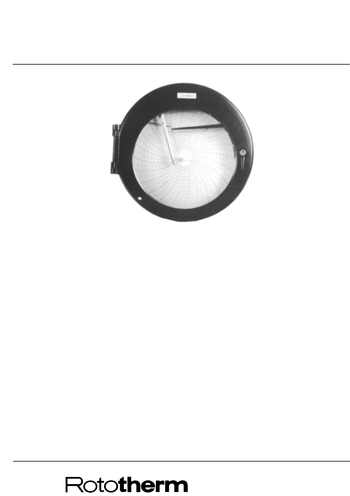
C105 Circular Case Recorder Operating Instructions Fig. 1. CONTENTS Page No. INTRODUCTION Identification Specification 2 2 3 INSTALLATION Mounting Access to Recorder Process Connections Electrical Connections 4 4 5 5 5 OPERATION Mechanical Clock Fitting a Chart Set Pointer Adjustment Inking System Zero Adjustment Start-up Check Start-up Procedure Description of Operation Electrical alarm/control system Programme Control 6 6 6 6 6 7 7 7 8 10 10 Page No.
INTRODUCTION The C105 series of instruments is designed to measure, record and control process variables such as temperature, pressure and humidity. A maximum of two measuring systems is provided in each instrument; a fluid expansion type or bimetallic system is used for temperature recording, a hygroscopic element or a wet and dry bulb system for humidity and a Bourdon tube or diaphragm for pressure measurement.
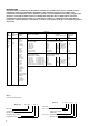
Specification General: 255mm Writing width 105mm Intrinsic error ± 1% span maximum (±2% R.H. for hygroscopic membrane system) Operating temperature limits –10o to +50oC Operating humidity limits 0 to 80% R.H. Zero error due to ambient temp. variations ±0.
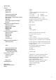
INSTALLATION Mounting The instrument can be wall or panel mounted using the same fixing brackets. Do not install near any very hot apparatus, e.g. ovens, steam pipes or flues. Mount the recorder vertically in a position free from vibration and excessive temperature. For panel mounting remove the fixing screws and rotate the fixing brackets so that the instrument can be inserted in the hole in the panel. Return the brackets to their original position and insert the fixing screws.
Access to Recorder To open the door, unlock, and turn the latch anticlockwise. As the door is opened the pen lifter raises the pen (or pens) away from the chart. Remove the chart (see page 6). If the instrument is connected to the mains, switch off the mains supply before dismantling further. For access to the terminal blocks remove the lower plastic plate from behind the chart by undoing the one retaining screw. For access to the relays and measuring systems, first remove the chart.
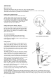
OPERATION Mechanical Clock To wind the mechanical clock first remove the chart as described below. This exposes the clock key, which is permanently fitted in the front recess of the clock moulding. To wind the clock turn the key clockwise. Do not overwind. Fitting a Chart (Spider Clamp) Unscrew the milled head on the centre of the clock spindle until the spider retracts. Remove the chart. Fit the new chart over the spider head onto the locating boss.
Zero adjustment NOTE: After making any zero adjustment to instruments fitted with control or alarm contacts the relay operating point must be checked and adjusted as described on page 10. Zero adjustment – temperature recorders and wet and dry bulb humidity instruments: All instruments are calibrated against a standard thermometer before despatch but should be checked in case of slight disturbance during transit. Immerse a standard thermometer with the bulb and check the readings.
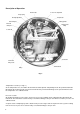
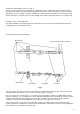
Description of Operation Bourdon tube Coarse zero adjustment Set-up spring Linearity adjustment Compensator Setting pointers Ratio arm pivot Drive link striker pin Setting pointer clamp Control unit Control arm Control unit fixing screws Terminal block Relays Fig. 5 Temperature recorder (see Fig. 5.) As the temperature rises, the fluid in the thermometer bulb expands and partially uncoils the spiral Bourdon tube fitted inside the instrument.
Temperature and humidity recorder (see Fig. 4) The air circulates around a strip of animal tissue (Goldbeater skin) the length of which varies with the relative humidity. The membrane is mounted under light spring tension and is connected by means of a bell crank lever and linkage to a pen arm which records the humidity on a calibrated chart. Temperature is measured by a fluid filled system which is mounted to the left of the humidity element and mechanically linked to a second pen arm.
Electrical alarm/control system Each relay is switched by a contact mounted on an arm linked to the setting pointer which makes or breaks with a contact attached to the recording pen linkage when the pen reaches the set point (see Fig. 5.). The striker is fixed relative to the pen arm and a spring loaded contact is fitted to the setting pointer linkage. One set of changeover contacts is available for external connection for each set point.
MAINTENANCE Cutting a programme cam The required programme should be drawn on to a spare recorder chart and transferred using carbon paper or a similar method to the paper covering on the cam blank. Mark on this trace significant points of the programme where the process state is important. Mark drilling centres on the radii of these programme points exactly 3mm out from the points. Drill through with a 6mm drill. Join up the programme points using a saw, and smooth off the profile between the points.
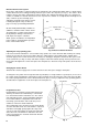
Calibration – Relative Humidity System (hygroscopic membrane) Switch off the electrical supply to the recorder. During manufacture the measuring element is calibrated in atmospheres of known equivalent relative humidity. These atmospheres are generated by specific salt solutions at constant temperature in apparatus which is unlikely to be available to the average instrument user.
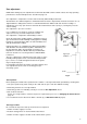
Wet and Dry Bulb Water Bath The wick should be changed frequently, the period between changes depending on the surrounding atmosphere. In wood drying kilns, etc., the wick should be renewed once a week but in clean atmospheres, e.g. offices, it can be left as long as three weeks. The water must be kept clean and free from impurities. 298.5 mm Bulb clamp For capillary entry from the right mount clamp A using holes B Optimum air flow direction Dry bulb Wet bulb with wick covering B. Mounting holes 13.
SPECIAL INSTRUCTIONS & DIAGRAMS 14
FAULT FINDING Recorder pen is inaccurate or gives no indication 1. Measuring element broken; capillary plugged or broken on temperature recorder. Check elements or capillary and replace as necessary. 2. Disconnected linkage in recorder. Re-connect or repair as necessary. 3. Recorder out of calibration, measuring element not damaged. Check and calibrate if necessary, pages 11 and 12. No record on chart 1. Pen not inking. Fit new pen capsule, page 6. 2. Chart drive motor stopped. Rewind, page 6.
SPARES LIST (continued) Description Part Number 6447448 Fig. 2 678 Fig. 8 Fig. 2 Fig. 10 Fig.