
Specifications


RotorWay International
Exec 162F Maintenance Manual
56
24. Rock the hub back and forth 15 to 20 times to set the shims and grease in their respective positions.
25. After reassembly, two objectives must be reached:
A. The hub must be on center of the main shaft.
B. The hub pressure must be between 8 to 12 lbs.
(This process is difficult to achieve on the first attempt).
26. Measure the hub pressure. Place a spring scale on the outboard pitch pin and pull up or down very slowly until the hub
breaks loose and moves. Note the poundage of pull required.
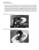
27. Measure the hub to shaft center position by using the hub fixture shown in photo #8. See drawing on page 59.
Photo #8: Hub alignment fixture and dial indicator.
This fixture is easy to fabricate and will give you very accurate results. Place the fixture on the hub. Push the fixture up
against the outboard pitch pins and hold the fixture down on the 3 rivet point contacts located on the bottom. Securely
hold the fixture on the hub and rock the hub slightly back and forth until the needle on the indicator stops moving in a
central position. Then zero the indicator. Carefully remove the fixture and place it on the other side of the hub using the
same procedures. Repeat the steps and determine how far the hub is off center, if any, and which direction it needs to
move. If all procedures were done correctly, you should not be any more than .002 to .004 off center and hub pressure
will still be within tolerance. Make a note on paper and determine which teeter block should be removed to center the
hub on the shaft. Change the stainless steel shims as necessary, following the procedures as previously outlined. The
tolerance and specs that must be achieved are:
A. Hub centering is within .001 T.I.R.
B. Hub pressure should be 8 to 12 lbs.
When the hub is correctly centered and hub pressure is within the limits specified, final assemble the hub. See photos
#9 through #13.