
Specifications


RotorWay International
Exec 162F Maintenance Manual
51
ROTOR HUB SHIMMING PROCEDURES
The EXEC 162F Rotor System will require hub shimming at different intervals depending upon how smoothly you keep
the rotor system adjusted. This section uses the “See-Do” concept like the Construction Manuals for clarification of the
maintenance to be performed.
SERVICE NOTES:
1. The following tools are required to preform the hub shimming procedures:
• 3/8" torque wrench in ft. lbs. capable of 30-35 ft. lbs.
• micrometer in thousandths of an inch
• 3/8" drive ratchet with 9/16" socket
• 9/16" box and open end wrench
• 1/4" punch with a 3" shank
• steel hammer and/or plastic hammer
• snap-ring pliers that will fit the holes on the snap rings
• spring scale
• set of allen wrenches or at least one 1/4" and one 1/8" allen wrench
• a clamp that spans the distance across the teeter blocks and has 4" jaws minimum
• one rotor hub shimming fixture. See page 59 in this manual for a drawing of the fixture with dimensions and
specifications. This fixture is also available from RotorWay, part number E08-6000.
• one dial indicator with a 4" reach that reads in thousandths.
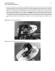
Photo #1: Tools required.
2. Start by removing the blades from the helicopter. Set the blades on their sides or on the leading edge. (Never set the
blades on the trailing edge.)
3. Turn the hub so that the numbers stamped on the hub plate are on the pilot side and the hub is aligned fore and aft to
the helicopter. It makes no difference which side of the helicopter the numbers are on, but it is good practice to
establish a normal and routine procedure.
4. Next, mark the hub and pitch links with a marker pen so they can be put back on exactly the way they were removed.
Mark the pitch links indicating which blade (master or slave) they attach to and also the up or down position. Then set
aside.