User's Manual
Table Of Contents
- 1. General Information
- 2. Technical Specifications
- 3. Installation
- 4. Wiring Instructions
- 5. Reader Functionality
- 5.1 Transmit Mode
- 5.2 Programming the AYC- F/G/M60 Series
- Programming Menu
- Entering Programming Mode
- Exiting Programming Mode
- Selecting Keypad Transmission Format
- Keypad Transmission Format Option Number
- Option 1: Single Key, 6-Bit Wiegand (Rosslare Format)
- Option 2: Single Key, 6-Bit Wiegand Nibble and Parities
- Option 3: Single Key, 8-Bit Wiegand Nibbles Complemented
- Option 4: 4 Keys Binary + Facility Code, 26-Bit Wiegand
- Option 5: 1 to 5 Keys + Facility Code, 26-Bit Wiegand
- Option 6: 6 Keys BCD and parity bits, 26-Bit Wiegand
- Option 7: Single Key, 3x4 Matrix Keypad (MD-P64)
- Option 8: 1 to 8 Keys BCD, Clock & Data
- Option 9: Single Key, 4-bit Wiegand
- Selecting Proximity Card Transmission Format
- Changing the Programming Code
- Changing the Facility Code
- Setting the Backlight and Reader Format
- Return to Factory Default Settings
- Replacing a Lost Programming Code
- 6. Controller Functionality
- 6.1 Normal, Secure, and Master Users
- 6.2 Modes of Operation
- 6.3 Auxiliary Input & Output
- 6.4 Door Alarms
- 6.5 Internal Case and Back Tamper
- 6.6 Lockout Feature (Keypad / Card Tamper)
- 6.7 Request to Exit (REX) Function
- 6.8 Secure Application Appurtenances
- 6.9 Programming the AYC- F/G/M60
- Programming Menu
- Entering Programming Mode
- Exiting Programming Mode
- Changing Lock Strike Code
- Changing Auxiliary Code
- Changing the Programming Code
- Changing the Normal / Secure Code
- Changing the Normal / Bypass Code and Door Chime Settings
- Setting Fail Safe/Secure Operation, Tamper Siren and Lock Strike Release Time
- Defining the Auxiliary Input and Output
- Quick Reference Guide for Auxiliary Mode Setting
- Detailed Reference Guide
- Setting the Lockout Feature
- Setting the backlight behavior
- Enrolling Primary and Secondary Codes
- Deleting Primary and Secondary Codes
- Relay Codes Assignment
- Relay Code Assignment using Search Method
- Pin Code Length / Factory Default Settings
- Replacing a Lost Programming Code
- Replacing a Lost Normal / Secure Code

AYC-Qx4 family manual
Page 31
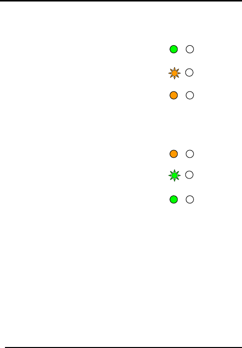
Changing from Normal Mode to Bypass Mode
See Changing the Normal / Bypass Code and Door Chime
Settings on page 38 to create/modify the Normal / Bypass code.
1) Enter the 4 digit Normal /
Bypass code
• Mode LED will flash
Orange
2) Press the “#” key to
confirm the mode change.
• Mode LED will turn orange
Changing from Bypass Mode to Normal Mode
See Changing the Normal / Bypass Code and Door Chime
Settings on page 38 to c
1) Enter the 4 digit Normal /
Bypass co
reate/modify the Normal / Bypass code.
de
e mode change.
put
, the controller’s
gured in ten different
s
erated by connecting the Auxiliary Input
Either Door-Forced or Door-Ajar
y one
• Mode LED will flash
green
2) Press the “#” key to
confirm th
• Mode LED will turn green
6.3 Auxiliary Input & Out
For optimum usability in different applications
auxiliary input and output can be confi
modes of operation.
6.4 Door Alarm
Door alarms can be gen
to a Door Position Switch.
conditions are supported, as well as, a configurable delay timer
for each alarm type. Only one Door-alarm is enabled at an
Mode/Transmit
Door/Program
Green
Mode/Transmit
Door/Program
Orange
Mode/Transmit
Door/Program
Oran
g
e
Mode/Transmit
Door/Program
Green
Mode/Transmit
Door/Program
Green
Mode/Transmit
Door/Program
Oran
g
e


