
Manual

40 © 2012, ROSS CONTROLS
®
. All Rights Reserved.
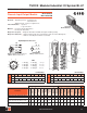
TURCK Modular Industrial I/O System BL 67
Electrical: • Operating Current: <35 mA from V
MB
<12 mA from V
Power Distribution: • Inputs: V
I
• Logic: V
MB
and V
I
Material: • Connectors: Nickel-plated brass
• Housing: PC-VO (Lexan)
Diagnostics (Logical):
• Diagnostic information available through the fieldbus gateway
Diagnostics (Physical):
• LED to indicate module bus communication status as well as I/O diagnostics
• LEDs for each I/O point to indicate on/off status
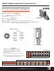
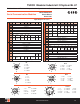
BL67-2AI-V
BL67-2AI-I
BL67-4AI-V/I
3.583
(91.0)
1.654 (42.0)
Diagnostic
LEDs
I/O LEDs
I/O
Connectors
1.260 (32.0)
7.677
(195.0)
5.709
(145.0)
1.260 (32.0)
1.654 (42.0)
3.583
(91.0)
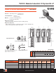
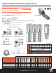
2 Analog Input Modules
Inputs Data
Part Number
Input
Count
Connectors Pinout
Inputs per
Connector
Sensor
Style
Group
Diagnostics
Individual
Diagnostics
Wire-Break
Detection
I/O Map
BL67-2AI-V with BL67-B-2M12* 2 0-1 B-AI 1 -10/0 to 10 V 1
BL67-2AI-I with BL67-B-2M12*
2 0-1 B-AI 1 0/4 to 20 mA 1
BL67-4AI-V/I with BL67-B-4M12*
4 0-3 B-AI 1 -10/0 to 10 V, 0/4 to 20 mA 2
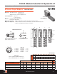
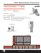
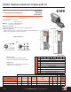
Input Connectors
B-AI
Loop Powered (Isolated) DeviceNet Powered Transducer
Mating cordset:
Isolated Loop: RK 4.5T-*M-RS 4.5T/S653
Loop Powered: RK 4.5T-*M-RS 4.5T/LPS/S653
Applications:
TURCK Sensors: LU; RK 4.4T-*-RS 4.4T/S1118
LI; RK 4.4T-*-*RS 4.4T/S1120
BL67-2AI-V/I
Modular I/O • Fieldbus Independent Configuration • IP 67 Protection • Various I/O Styles
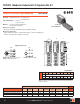
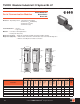
I/O Data Map 1
In
Byte Bit 7 Bit 6 Bit 5 Bit 4 Bit 3 Bit 2 Bit 1 Bit 0
n-1 (Data from modules to the left)
n Channel 0, LSB
n+1 Channel 0, MSB
n+2 Channel 1, LSB
n+3 Channel 1, MSB
n+4 Channel 2, MSB
n+5 Channel 2, MSB
n+6 Channel 3, MSB
n+7 Channel 3, MSB
n+8 (Data from modules to the right)