
Manual

39www.rosscontrols.com
TURCK Modular Industrial I/O System BL 67
Serial Communication Modules
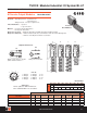
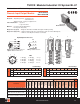
B2
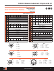
1 = NC
2 = TxD
3 = Gnd
ISO
4 = RxD
5 = Shield
B2-8
1 = RxD
2 = TxD
3 = RTS
4 = CTS
5 = Gnd
ISO
6 = NC
7 = NC
5 = Shield
B4
1 = Tx
2 = Tx+
3 = Rx-
4 = Rx+
5 = Shield
B4-8
1 = Rx+
2 = Tx+
3 = Tx-
4 = NC
5 = Rx-
6 = Gnd
ISO
7 = NC
5 = Shield
SSI
1 = V-
2 = V
I
+
3 = CLK+
4 = CLK-
5 = DATA+
6 = DATA-
7 = NC
8 = Shield
SSI-23
1 = V-
2 = V
I
+
3 = CLK+
4 = CLK-
5 = DATA+
6 = DATA-
7 = NC
8 = Shield
9 = NC
10 = NC
11 = NC
12 = NC
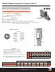
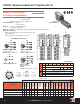
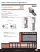
Input/Output Connectors
In
Byte Bit 7 Bit 6 Bit 5 Bit 4 Bit 3 Bit 2 Bit 1 Bit 0
n-1
(Data from modules to the left)
n
Data Byte 5 (MSB)
n+1
Data Byte 4
n+2
Data Byte 3
n+3
Data Byte 2
n+4
Data Byte 1
n+5
Data Byte o (LSB)
n+6
Buf
Ovfl
Frame
Err
HndSh
Err
HW
Failure
Prm
Err
Reserved
n+7
STAT
TX_CNT_
ACK
RX_CNT
RX_BYTE_
CNT
n+8
(Data from modules to the right)
Out
n-1
(Data from modules to the left)
n
Data Bytes 5 (MSB)
n+1
Data Bytes 4
n+2
Data Bytes 3
n+3
Data Bytes 2
n+4
Data Bytes 1
n+5
Data Bytes 0 (LSB)
n+6
Reserved
RxBuf
Flush
TxBuf
Flush
n+7
STAT
Res
RX_CNT_
ACK
TX_
CNT
TX_BYTE_
CNT
n+8
(Data from modules to the right)
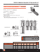
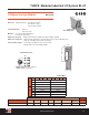
In
Byte Bit 7 Bit 6 Bit 5 Bit 4 Bit 3 Bit 2 Bit 1 Bit 0
n-1
(Data from modules to the left)
n
STOP X X
ERR
PARA
UFLW OFLW
ERR
SSI
SSI
DIAG
n+1
UP DN
REL
CMP2
FLAG
CMP2
STS
CMP2
REL
CMP1
FLAG
CMP1
STS
CMP1
n+2
REG WR
ACPT
REG WR
ACK
X X
SSI
STS3
SSI
STS2
SSI
STS1
SSI
STS0
n+3
REG RD
ABRT
X REG_RD_ADR
n+4
REG_RD_DATA, Byte 0
n+5
REG_RD_DATA, Byte 1
n+6
REG_RD_DATA, Byte 2
n+7
REG_RD_DATA, Byte 3
n+8
(Data from modules to the right)
Out
n-1
(Data from modules to the left)
n
STOP X X X X X X X
n+1
X X X
CLR
CMP2
EN
CMP2
X
CLR
CMP1
EN
CMP1
n+2
REG WR X REG_WR_ADR
n+3
X X REG_WR_ADR
n+4
REG_WR_DATA, Byte 0
n+5
REG_WR_DATA, Byte 1
n+6
REG_WR_DATA, Byte 2
n+7
REG_WR_DATA, Byte 3
n+8
(Data from modules to the right)
Modular I/O • Fieldbus Independent Configuration • IP 67 Protection • Various I/O Styles
BL67-1RS485/422
BL67-1RS232
BL67-1SSI