
Manual

29www.rosscontrols.com
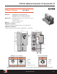
TURCK Modular Industrial I/O System BL 67
4 Discrete Output Modules
Electrical: • Operating Current: <30 mA from V
MB
<100 mA from V
O
• Output Current: <0.5 A per output from V
O
Power Distribution: • Inputs: V
O
• Logic: V
MB
and V
O
Material: • Connectors: Nickel-plated brass
• Housing: PC-VO (Lexan)
Diagnostics (Logical): • Diagnostic information available through the fieldbus gateway
Diagnostics (Physical): • LED to indicate module bus communication status as well as I/O diagnostics
• LEDs for each I/O point to indicate on/off status
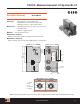
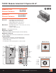
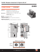
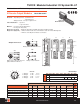
BL67-4DO-0.5A-P
D
A B C
3.583
(91.0)
1.654 (42.0)
Diagnostic
LEDs
I/O LEDs
I/O
Connector
1.260 (32.0)
7.677
(195.0)
5.709
(145.0)
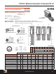
Outputs Data
Part Number Drawing
Output
Count
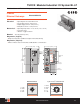
Connectors Pinout
Outputs per
Connector
Current Style
Individual
Diagnostics
I/O
Map
BL67-4DO-0.5A-P with BL67-B-4M12* A 4 0-3 G 1 0.5 A Source 1
BL67-4DO-0.5A-P with BL67-B-2M12* B 4 0-1 2G 2 0.5 A Source 1
BL67-4DO-0.5A-P with BL67-B-2M12-P* B 4 0-1 2G 2 0.5 A Source 1
BL67-4DO-0.5A-P with BL67-B-4M8* D 4 0-3 PO 1 0.5 A Source 1
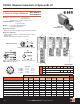
BL67-4DO-0.5A-P with BL67-B-1M23* C 4 0 M23-4O 4 0.5 A Source 1
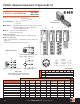
2G
Mating cordset: RK 4.4T-*-RS 4.4T
Splitter: VBRS 4.4-2RK 4T-*/*
PO
Mating cordset: PSG 3M-*
G
Mating cordset: RK 4.4T-*-RS 4.4T
M23-4O
1 = Output
0
2 = Output
1
3 = Output
2
4 = Output
3
5 = NC
6 = NC
7 = NC
8 = NC
9 = V
I
+
10 = V
I
+
11 = V
I
+
12 = V-
1
4
3
5
2
6
7
8
9
10
11
12
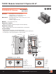
Outputs Connectors
I/O Data Map 1
Shown with
BL67-B-4M12 base
Out
Byte Bit 7 Bit 6 Bit 5 Bit 4 Bit 3 Bit 2 Bit 1 Bit 0
n-1 (Data for modules to the left)
n Data for next discrete modules 0-3 0-2 0-1 0-0
n+1 (Data for modules to the right)
Modular I/O • Fieldbus Independent Configuration • IP 67 Protection • Various I/O Styles