
User Manual


10 ROSS CONTROLS
®
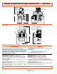
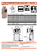
Sizes 8, 12, 30
C
A
B
3
2
1
D-S MONITOR
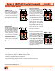
Wiring Diagram
ABCDEFGHJK
ab
POW ER
SOL . a
POWER
SOL. b
MONITOR
POWER
RESET
SWITCH
FAULT
INDICATOR
D-S MONITOR
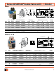
Port Valve Model Number Avg. C
V
Dimensions inches (mm) Weight
Size Size w/ Overrides w/o Overrides In-Out Out-Exh. A B C lb (kg)
8 1/2 3573B4143 3573B4163 3.5 8.5 8.5 (216) 7.2 (184) 16.5 (418) 16.8 (7.6)
8 3/4 3573B5143 3573B5163 4.0 12 8.5 (216) 7.2 (184) 16.5 (418) 16.8 (7.6)
12 3/4 3573B5153 3573B5173 8.0 15 9.0 (229) 8.6 (219) 17.8 (451) 20.5 (9.2)
8 1 3573B6153 3573B6173 4.0 12 8.5 (216) 7.2 (184) 16.5 (418) 16.8 (7.6)
12 1 3573B6163 3573B6183 8.5 19 9.0 (229) 8.6 (219) 17.8 (451) 20.5 (9.2)
12 1¼ 3573B7163 3573B7183 9.0 21 9.0 (229) 8.6 (219) 17.8 (451) 20.5 (9.2)
30* 1¼ 3573B7153 3573B7173 20 42 12.4 (314) 11.1 (282) 21.8 (553) 39.3 (17.7)
30* 1½ 3573B8163 3573B8183 21 43 12.4 (314) 11.1 (282) 21.8 (553) 39.3 (17.7)
Valves Models without Piping Flanges (For replacement purposes)
8 All 3573B4203 3573B4223
See corresponding size
15.3 (6.9)
12 All 3573B5203 3573B5223
above.
19.0 (8.6)
30 All 3573B7203 3573B7223 37.8 (17.2)
*2 inch port size available on size 30 valves. Order part number 1999H77 flange kit separately.
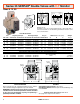
Series 35 SERPAR
®
Double Valves with D-S Monitor
A
C
(4 places)
B
Port 1
(inlet)
3/4 NPSC
electrical
opening
Port 2
(outlet)
H
Momentary Reset Switch
with no power applied.
(supplied by customer)
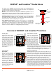
VALVE OPERATION
Both solenoids must be energized simultaneously to shift the
valve; maintained signal required to keep valve shifted.
WARNING: If monitor must be reset, electrical signals to both
solenoids must be removed to prevent the machine controlled
by the valve from immediately recycling and producing a
potentially hazardous condition.
OPTIONS
Valve Without Piping Flanges: See above.
Valve Without Silencer: Exhaust port has threaded flange only.
Consult ROSS.
Valve Response Time (msec)
= M + F • V
See page 18 for response time values.