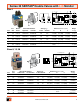
BULLETIN 380 • Manufacturers of Premium Pneumatic Controls since 1921 •
Contents Double Valves Overview The Leader in Double Valves Design...........................................................................................................3 ROSS Double Valves...................................................................................................................................3 Why Use A Double Valve?...........................................................................................................................3 SERPAR® and CrossflowTM Double Valves.
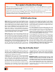
The Leader in Double Valve Design ROSS has long been in the forefront of double valve research and development. For over 54 years ROSS has been responding to the needs of press manufacturers by supplying double valves of different types. Internal flow patterns have included series flow, parallel flow, and combined series flow. Monitoring devices have also been offered in a variety of designs to satisfy differing requirements.
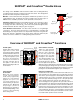
SERPAR® and CrossflowTM Double Valves The design of the SERPAR® and CrossflowTM double valve is distinguished by crossflow passages and spool valving on the main valve stems. This arrangement provides the valve’s unique flow characteristics. Delrin Piston Buna N Lip Seal Monitors: Self-contained monitors, designed to inhibit valve operation in case of a fault within the valve, are built into the valve assembly.
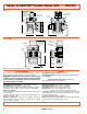
Series 35 SERPAR® Double Valves with L-G Monitor Size 4 YC YA 1 3 YD YB Manual Reset C B L (Lockout Indicator) A Port Monitor Size Size Reset 4 3/8 Manual 4 3/8 Remote 4 1/2 Manual 4 1/2 Remote 4 3/4 Manual 4 3/4 Remote 4 All Manual 4 All Remote 2 YE Valve Model Numbers Average CV* Dimensions inches (mm) Right Inlet Left Inlet In-Out Out-Exh. A B C 3573D3191 3573D3195 3.0 6.0 7.4 (188) 6.3 (160) 7.4 (188) 3573D3192 3573D3196 3.0 6.0 7.4 (188) 6.3 (160) 7.4 (188) 3573D4211 3573D4215 3.
Series 35 SERPAR® Double Valves with L-G Monitor Size 4 1/8 Remote pneumatic reset port or manual reset 10-32 Lockout Indicator Port 1/8” Lockout Indicator Port 7.8 (0.31) 2 places Inlet or outlet port Left Side C Right Side B A Size 8, 12, 30 1/8 external pilot supply port (4 places) 1/8 Lockout indicator 1/8 pneumatic reset port Port 2 (outlet) C Port 1 (inlet ) 1/2 NPSC electrical opening A B NOTE: For external pilot models consult ROSS.
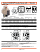
Series 35 SERPAR® Double Valves with L-G Monitor Overview of Valve Function Pb Conditions at start: Inlet 1 is closed to outlet 2 by both valve elements A and B. Outlet 2 is open to exhaust 3. Pilot air is ported from inlet 1 and through the center section of spool S to the normally closed pilots Pa and Pb. Monitoring pressure signals at both ends of spool S are exhausted.
Series 35 SERPAR® Double Valves with E-P Monitor a 5 6 7 8 9 1 2 3 4 5 6 7 8 9 a b c c Single Input Wiring Diagram Dual Input Wiring Diagram During lock-out: Terminals 3 and 7 are connected which allows a panel light, bell, or other electrical device to be wired through terminals 7 and 3 to serve as a lockout indicator. A Port Size Size Valve Model Number Single Signal Input Dual Signal Input Avg.
Series 35 SERPAR® Double Valves with E-P Monitor Overview of Valve Function Conditions at start: Inlet 1 is closed to outlet 2 by both valve elements A and B. Outlet 2 is open to exhaust 3. Contacts of switch SW are closed. Monitoring pressure signals at both ends of spool S are exhausted. Pb 3 2 B A 1 Normal operation: Simultaneously energizing both solenoids actuates both pilots and causes valve elements A and B to shift. Inlet 1 is then connected to outlet 2 via crossflow passages C and D.
Series 35 SERPAR® Double Valves with D-S Monitor Sizes 8, 12, 30 3 b H D-S MONITOR C B a 2 1 A B C D E F G H J K POWER POWER MONITOR RESET FAULT SOL.a SOL.b POWER SWITCH INDICATOR Momentary Reset Switch with no power applied. (supplied by customer) Wiring Diagram D-S MONITOR A Port Size Size 8 1/2 8 3/4 12 3/4 8 1 12 1 12 11/4 30* 11/4 30* 11/2 8 12 30 All All All Valve Model Number Avg. CV Dimensions inches (mm) w/ Overrides w/o Overrides In-OutOut-Exh. A B C 3573B4143 3573B4163 3.5 8.
Series 35 SERPAR® Double Valves with D-S Monitor Overview of Valve Function Conditions at start: Inlet 1 is closed to outlet 2 by both valve elements A and B. Outlet 2 is open to exhaust 3. Contacts of switch SW are closed. Monitoring pressure signals at both ends of spool S are exhausted. Normal operation: Simultaneously energizing both solenoids actuates both pilots and causes valve elements A and B to shift. Inlet 1 is then connected to outlet 2 via crossflow passages C and D. Exhaust 3 is closed.
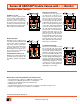
Series 35 CrossflowTM Double Valves with Pressure Switches* Size 1 & 2 * Non-monitored B B C C A CrossflowTM Size 1 A CrossflowTM Size 2 Valve Assembly Valve Model Avg. CV Pressure Press. Switch Port Sizes Size Number* 1-2 2-3 Switches** Provision 1 & 2 3 1 3573B2632 0.9 1.4 None Yes 1/4 1/4 1 3573B2640 0.9 1.4 None No 1/4 3/8 1 3573B2642 0.9 1.4 Two Yes 1/4 1/4 1 3573B2644 1.2 1.7 Two Yes 3/8 3/8 1 3573B2645 1.2 1.7 None Yes 3/8 3/8 2 3573B4620 3.7 6.6 None No 1/2 1/2 2 3573B4632 3.7 6.
Series 35 CrossflowTM Double Valves with Pressure Switches* VALVE Dimensions inches (mm) Size 2 Size 1 2.8 (72) 1.76 (45) 6.3 (160) 5.0 (127) 1.78 (45.2) 0.87 (22) 0.78 (20) 2.38 (60.3) 2.7 (69) 0.16 (4) 0.25 (6.4) 1.56 (40) 0.16 (4) 0.25 (6.4) 2.85 (72.3) 3.4 (86) 1.8 (46) BASE Dimensions inches (mm) Size 1 Size 2 E A K A B C N 3 J M 2 E K B 3 F* C 1 M J 2 F* 1 D G L H G D L H NOTE: Add 2.6” (67 mm) to dimension F for models with pressure switches.
Series 35 CrossflowTM Double Valves with Pressure Switches* Size 4, 8, 12, 30 3 2 1 Size 4 Size 8, 12, 30 Model Number*Standard Flow Port Flanged Ports Avg. CV Dimensions inches (mm) Size Size Inlet Right Inlet Left 1-2 3-4 A B C 4 3/8 3573C3270 3573C3276 3 7 Valve Weight lb (kg) 8.2 (209) 6.1 (155) 7.6 (195) 8.4 (3.8) 4 1/2 3573C4270 3573C4276 3 9 8.2 (209) 6.1 (155) 7.6 (195) 8.4 (3.8) 4 3/4 3573C5230 3573C5236 3 11 8.2 (209) 6.1 (155) 7.6 (195) 8.4 (3.
Series 35 CrossflowTM Double Valves with Pressure Switches* Dimensions inches (mm) Size 4 7.2 (185) 4.7 (119) 6.1 (155) Threaded-port model 7.4 (189) Flanged-port model G 3/8 - G1/2 8.2 (209) Flanged-port model G 3/4 Size 8, 12, 30 C A B Treaded-port model A Flanged-port model Size A (Flanged-port model) 8 8.8 (224) Dimensions inches (mm) A (Threaded-port model) B C 6.7 (172) 7.2 (184) 11.2 (284) 12 9.1 (230) 7.0 (178) 8.6 (219) 12.4 (316) 30 12.4 (315) 10.3 (267) 11.
Series 35 CrossflowTM Double Valves with Pressure Switches* Overview of Valve Function Pb Conditions at start: Inlet 1 is closed to outlet 2 by both valve elements A and B. Outlet 2 is open to exhaust 3. Pressure signals at both switches SWA and SWB are exhausted. Contacts 1 and 2 of switches SWA and SWB are connected. Pa B A 2 Normal operation: Simultaneously energizing both solenoids actuates both pilots and causes valve elements A and B to shift.
Accessories ELECTRICAL CONNECTORS RESET VALVES for L-G Monitor Electrical connectors are required to connect the valve solenoids to the drop cords supplying electrical power. Each connector can be positioned so that the cord exits upward or to the side. Cords of 6 mm to 10 mm diameter can be used. Connectors with a light in a translucent housing are also available to serve as indicator lights. Order connectors by the part numbers given in the chart below.
General Information VALVE RESPONSE TIMES Most pneumatic applications call for a valve to be used to control the repeated filling and exhausting device (cylinder, clutch, etc.) having a certain volume. The time required to fill or exhaust this volume is called the “valve response time.” The time to fill a volume is usually different from the time to exhaust the volume.
Cautions PRE-INSTALLATION or SERVICE 1. Before servicing a valve or other pneumatic component, be sure that all sources of energy are turned off, the entire pneumatic system is shut off and exhausted, and all power sources are locked-out (ref: OSHA 1910.147, EN 1037). 2. All ROSS products, including service kits and parts, should be installed and/or serviced only by persons having training and experience with pneumatic equipment.
GLOBAL Reach with a LOCAL Touchsm ROSS CONTROLS ROSS SOUTH AMERICA Ltda. Troy, MI., U.S.A. Telephone: + 1-248-764-1800 Fax: + 1-248-764-1850 In the United States: Customer Service: 1-800-GET ROSS (438-7677) Technical Service: 1-888-TEK-ROSS (835-7677) www.rosscontrols.com São Paulo, Brazil CEP 09725-020 Telephone: + 55-11-4335-2200 Fax: + 55-11-4335-3888 Email: vendas@ross-sulamerica.com.br DIMAFLUID s.a.s.
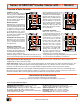
New Product Information SERPAR® Crossflow Double Valves with Dual Monitoring Includes Both L-G and E-P Monitors – Sizes 8, 12, & 30 CSA Z142 Compliant Size 8 STANDARD SPECIFICATIONS Pilot Solenoid: Two, rated for continuous duty. Standard Voltages: 100 – 110 volts 50 Hz; 100 – 120 volts 60 Hz; 24 volts d.c. Power Consumption: Each solenoid, 87 VA inrush, 30 VA holding on 50 or 60 Hz; 14 watts on d.c. Reset Solenoid (E-P): Rated for intermittent duty. Standard Voltages: Same as above for pilot solenoids.
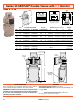
VALVE MODEL NUMBERS and MODEL SPECIFIC INFORMATION Nominal Size Port Size 8 Model Numbers Avg. Response Constants Average CV 2 to 3 1 to 2 With Overrides Without Overrides 1/2 3/4 1 3573A4148 3573A5148 3573A6158 3573A4168 3573A5168 3573A6178 3.5 4.0 4.0 10 14 14 12 3/4 1 1-1/4 3573A5158 3573A6168 3573A7168 3573A5178 3573A6188 3573A7188 8.0 8.5 9.