
Manual
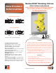
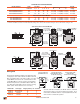

3/2 Solenoid Pilot Controlled Models
3/2 Pressure Controlled Models
Port PV
(pressure
verification)
1/8” Signal Port
B
A
C
2X O 0.53 (13.5)
Port 1(inlet)
[Port 2 (outlet
on opposite site]
Port 3
(exhaust)
5-pin M12
connector
3-pin Mini
connector
C
A
B
2X O 0.53 (13.5)
Port PV
(pressure
verification)
Port 3
(exhaust)
Port X-1
(1/8 external
pilot supply)
Port 1(inlet)
[Port 2 (outlet
on opposite site]
5-pin M12
connector
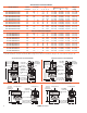
Solenoid Pilot Controlled Models
Model Numbers* Valve Port Size C
v
Dimensions inches (mm)
Weight
Function
1, 2 3 1 - 2 2 - 3 A B C lb (kg)
SV27NC309807PSAA1A** 3/2 1½ 2½ 68 70 8.7 (219) 11.8 (300) 6.4 (161) 18.1 (8.2)
SV27NC309907PSAA1A** 3/2 2 2½ 70 70 8.7 (219) 11.8 (300) 6.4 (161) 18.1 (8.2)
SV27NC309957PSAA1A** 3/2 2½ 2½ 70 71 8.7 (219) 11.8 (300) 6.4 (161) 18.1 (8.2)
Pressure Controlled Models
SV27NC309805ASAA 3/2 1½ 2½ 68 70 8.7 (219) 11.8 (300) 6.4 (161) 17.2 (7.8)
SV27NC309905ASAA 3/2 2 2½ 70 70 8.7 (219) 11.8 (300) 6.4 (161) 17.2 (7.8)
SV27NC309955ASAA 3/2 2½ 2½ 70 71 8.7 (219) 11.8 (300) 6.4 (161) 17.2 (7.8)
*NPT port threads. For BSPP threads, replace “N” in the model number with a “D”.
** “1A”=120 volts 60Hz, solenoids. For 240 volts 60 Hz, change “1A” to “2A”; for 24 volts 60 Hz, change to “3A”; for 24 volts DC, change to “1D”.
www.rosscontrols.com 3
2
13
PV
12
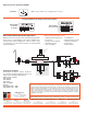
Wiring Kits
BRN
PIN 1
BLUE
PIN 3
BLK
PIN 4
GRY
PIN 5
WHT
PIN 2
BLUE
BRN
BLK
WHT
GRAY
Current/Voltage Max. 2.5 A /120 VAC
Sensing Switch Cable
with 5-pin M12 Connector
for 3/4 and 1¼ bodies.
BRN
PIN 3
BLUE
PIN 2
GRN/YEL
(GROUND)
PIN 1
BRN
BLUE
GRN/YEL
Solenoid Cable with
3-pin MINI Connector
Sensing Switch Cable
with 5-pin M12
Connector for 2 inch body.
These kits are available in lengths of 4 or 10 meters, with
a cord grip on each cable. The kits for SV27 solenoid
pilot controlled models come with 2 cables; one with
a 3-pin MINI connector for the solenoid and one with
a 5-pin M12 (Micro) connector for the sensing switch.
The kits for the pressure controlled models include only
one cable with a 5-pin M12 connector for the sensing
switch. (Note: Each cable has one connector.)
Kit Number Valve Type Length (meters) No. of Cables
2239H77 Solenoid Pilot 4 2
2240H77 Solenoid Pilot 10 2
2241H77 Air Pilot 4 1
2242H77 Air Pilot 10 1
*For 3/4 and 1¼ inch bodies, the DPST switch is actuated
whenever the valve is not in the normal home position. For 2
inch bodies, the DPST switch is only actuated whenever the
valve is in the normal home position.
BRN
PIN 1
BLUE
PIN 3
BLK
PIN 4
GRY
PIN 5
WHT
PIN 2
Current/Voltage Max. 2.5 A /120 VAC