
Owner manual

Printed in the U.S.A. – Rev. 07/12 © 2012, ROSS CONTROLS
®
. All Rights Reserved. Form NPS015
WARRANTY and CAUTIONS
Standard ROSS warranty and cautions apply, available upon request or at www.rosscontrols.com
ROSS EUROPA GmbH
Germany
Fax: 49-6103-74694
info@rosseuropa.com
ROSS ASIA
®
K.K.
Japan
Fax: 81-427-78-7256
custsvc@rossasia.co.jp
ROSS UK Ltd.
United Kingdom
Fax: 44-121-559-5309
sales@rossuk.co.uk
ROSS SOUTH AMERICA Ltda.
Brazil
Fax: 55-11-4335-3888
vendas@ross-sulamerica.com.br
ROSS CONTROLS
®
INDIA Pvt. Ltd.
India
Fax: 91-44-2625-8730
rossindia@airtelmail.in
DIMAFLUID s.a.s.
France
Fax: 33-01-4945-6530
dimafluid@dimafluid.com
ROSS CONTROLS
(CHINA) Ltd.
China
Fax: 86-21-6915-7960
alvinzhurong@vip.163.com
ROSS CONTROLS
®
U.S.A.
Customer Svs. 1-800-GET-ROSS
Technical Svs. 1-888-TEK-ROSS
www.rosscontrols.com
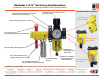
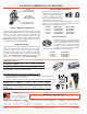
AIR ENTRY COMBINATION ACCESSORIES
CLAMP for MODULE CONNECTIONS
Specially designed clamps provide a quick and easy assembly
or disassembly of MD3 modules. Two allen-head bolts quickly
tighten or loosen the clamp using a 5/32 or 4mm hex key.
The clamp contains a plate carrying two O-rings to provide
positive sealing between modules. Order clamp by part number
R-A118-105. Combined clamp and bracket (below) can be
ordered by part number R-A118-105M.
MOUNTING BRACKET
Two brackets are normally used to mount an FRL to a vertical
surface. The mounting bracket attaches to the module-
connecting clamp (see above) with a single screw. Each
bracket then employs two bolts (1/4” or 6mm) to connect the
assembly to the mounting surface. Order bracket and screw
by part number R-A118-103. Combined bracket and
clamp
(above) can be ordered by part number R-A118-105M.
Mounting Bracket
Part No. R-A118-103
EXTRA PORT BLOCK
An extra port block can be placed between
modules to provide two auxiliary 1/4 NPTF
ports. Its mounting position can be rotated
to obtain the most convenient operating
orientation. If only one auxiliary port is to be
used, the unused port must be closed with
a pipe plug. (The inlet and outlet are not threaded.)
Port Size Part Number
1/4 NPTF ................R-118-106-2
3/8 NPTF ................R-118-106-3
1/2 NPTF ................R-118-106-4
Module
Connecting Clamp
Part No. R-A118-105
Combined
Clamp & Bracket
Part No. R-A118-105M
MALE and FEMALE END PORTS
Either male or female end ports can
be attached to threaded inlet and
outlet lines. This allows all modules
of an FRL assembly to be removed
easily and quickly without having
to unthread the end modules. The
end ports are attached to the modules with clamps (see at left).
End ports can be included in an assembled FRL or ordered
separately by the following part numbers:
Port Size Male Number Female Number
1/4 NPTF R-118-109-2F R-118-100-2
3/8 NPTF R-118-109-3F R-118-100-3
1/2 NPTF R-118-109-4F R-118-100-4
3/4 NPTF R-118-109-6F R-118-100-6
Female
Male
MUFFL-AIR
®
Silencer
MUFFL-AIR
®
Silencer
• May be installed on all L-O-X
®
valves and manual L-O-X
®
valves with EEZ-ON
®
operation with pressure sensing port
• Provides a means to verify the release of downstream pressure to next obstruction
Visual Pop-Up Indicator or Pressure Switch (electrical)
Pop-Up
Indicator
Pressure Switch
Model Inlet Port Verification Dimensions inches (mm) Weight
Number Size* Option A B C lb (kg)
988A30 1/8 Pop-Up Indicator 0.55 (14) 0.98 (25) – 0.03 (0.01)
586A86 1/8 Pressure Switch 2.01 (51) 4.3 (110) 1.22 (31) 0.28 (0.12)
* NPT port threads.
A
B
C
A
B
A
B
Port NPT Model Avg. Dimensions inches (mm) Weight
Size Threads Number C
V
A B lb (kg)
3/4 Male 5500A5013 7.0 1.3 (32) 3.8 (96) 0.5 (0.2)
* NPT port threads. For BSPP threads, add the letter “D” in front of the part number.
Pressure Range: 150 psig (10.3 bar) maximum.