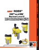
ROSS CONTROLS® • ROSS CONTROLS® • ROSS CONTROLS® • Manufacturers of Premium Pneumatic Controls since 1921 •
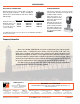
DM 1 Series E New Product Introduction Control Reliable Double Valve with Dynamic Monitoring Size 2 Simplified Schematic Port Size CV Weight Model Number* In-Out Exh. In-Out Out-Exh. lb (Kg) DM1ENA20**31 DM1ENA21**31 1/4 3/8 1/2 1/2 1.34 2.43 1.92 2.43 5.0 (2.27) 5.0 (2.27) * NPT port threads. For BSPP threads , replace “N” in the model number with a “D”. ** Insert voltage code: “A” = 24 volts DC, “B” = 110 volts AC, “C” = 220 volts AC, “D” = 12 volts DC.
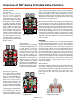
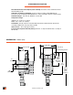
Overview of DM 1 Series E Double Valve Function Valve de-actuated (ready-to-run): The flow of inlet air pressure into the crossover passages from the inlet chamber is restricted by orifices that allow air pressure to bypass the lower inlet poppets. Flow is sufficient to quickly pressurize the pilot supply/timing chambers on both sides A and B. The upper inlet poppets prevent air flow from the crossover passages into the outlet chamber.
STANDARD SPECIFICATIONS Pilot Solenoid Power Consumption (each solenoid): 6.0 watts on DC; 15.8 VA inrush and 10.4 VA holding on AC. Solenoids: According to VDE 0580. Enclosure rating according to DIN 400 50 IP 65. Connector socket according to DIN 43650 Form A. Three solenoids, rated for continuous duty. Standard Voltages: 110 volts AC, 50/60 Hz; 24 volts DC. Temperature Range: Ambient: 15° to 122°F (4° to 50°C). Media: 40° to 175°F (4° to 80°C).
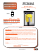
ACCESSORIES ELECTRICAL CONNECTORS STATUS INDICATOR Wired connectors have a 2-meter (61/2 ft) cord with three 18-gauge conductors. Cord is available in either 6-mm or 10-mm diameter and with or without indicator light. The Status Indicator pressure switch actuates when the valve is in a ready-to-run condition and de-actuates when the valve is in a lockout condition or when the inlet air pressure has been removed.
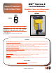
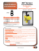
DM 2® Series E New Product Introduction Control Reliable Double Valve with Dynamic Monitoring & Memory Size 2 Simplified Schematic Port Size CV Weight Model Number* In-Out Exh. In-Out Out-Exh. lb (Kg) DM2ENA20**21 DM2ENA21**21 1/4 3/8 1/2 1/2 1.34 2.43 1.92 2.43 5.6 (2.43) 5.6 (2.43) * NPT port threads. For BSPP threads replace “N” in the model number with a “D”. ** Insert voltage code: “A” = 24 volts DC, “B” = 110 volts AC, “C” = 220 volts AC, “D” = 12 volts DC.
Overview of DM2® Series E Double Valve Function Valve de-actuated (ready-to-run): The flow of inlet air pressure into the crossover passages from the inlet chamber is restricted by orifices that allow air pressure to bypass the lower inlet poppets. Flow is sufficient to quickly pressurize the pilot supply/timing chambers on both sides A and B. The upper inlet poppets prevent air flow from the crossover passages into the outlet chamber.
STANDARD SPECIFICATIONS Pilot Solenoid Power Consumption (each solenoid): 6.0 watts on DC; 15.8 VA inrush and 10.4 VA holding on AC. Solenoids: According to VDE 0580. Enclosure rating according to DIN 400 50 IP 65. Connector socket according to DIN 43650 Form A. Three solenoids, rated for continuous duty. Standard Voltages: 110 volts AC, 50/60 Hz; 24 volts DC. Reset Solenoid Power Consumption: 6.0 watts on DC; 15.8 VA inrush and 10.4 VA holding on AC.
ACCESSORIES ELECTRICAL CONNECTORS STATUS INDICATOR Wired connectors have a 2-meter (61/2 ft.) cord with three 18-gauge conductors. Cord is available in either 6-mm or 10-mm diameter and with or without indicator light. The Status Indicator pressure switch actuates when the valve is in a ready-to-run condition and de-actuates when the valve is in a lockout condition or when the inlet air pressure has been removed.
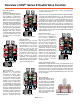
DM 2® Series C New Product Introduction Control Reliable Double Valve with Dynamic Monitoring & Memory Sizes 4, 8, 12 and 30 Simplified Schematic Valve Size 4 8 8 12 30 Port Size Model Number* Inlet Outlet DM2CNA42**21 DM2CNA54**21 DM2CNA55**21 DM2CNA66**21 DM2CNA88**21 1/2 3/4 1 1 11/2 1/2 3/4 1 1 2 CV Weight 1 to 2 lb (Kg) 3 5.9 (2.6) 4.4 8.4 (3.7) 4.4 8.4 (3.7) 8.5 15.3 (6.7) 22 34.7 (15.1) * NPT port threads.
Overview of DM2® Series C Double Valve Function The flow of inlet air pressure into the crossover passages is restricted by the size of the passage between the stem and the valve body opening. Flow is sufficient to quickly pressurize pilot supply/timing chambers A and B. The inlet poppets prevent air flow from crossover passages into the outlet chamber. Air pressure acting on the inlet poppets and return pistons securely hold the valve elements in the closed position.
STANDARD SPECIFICATIONS Pilot solenoid: According to VDE 0580. Rated for continuous duty. Standard voltages: 24 volts DC, 110 volts AC (50/60 Hz), 220** VAC (50/60 Hz). For other voltages consult ROSS. ** 220 volts AC not available in the U.S. (OSHA regulations limit press control voltage to no more than 120 volts AC. Power consumption (each solenoid): Size 4, 12, 30: Primary and reset solenoids: 5.8 watts on DC; 15.8 VA inrush and 12.8 VA holding on AC.
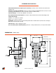
SIZE 12 DIMENSIONS – inches (mm) Main Solenoids Status Indicator 9.42 (239.3) 6.74 (117.2) View X (Base mounting hole pattern) Valve envelope (Based in overall hole dimnsions at left.) 1/2 NPT Outlet Port (Each Side) 5.86 (148.8) 1.67 (42.4) 13.23 (336.1) 13.71 (348.3) 0.42 (10.7) (4 places) 7.47 (189.7) 2.36 (59.9) 0.57 (14.5) 2.07 (52.6) 4.72 (119.9) 1/2 NPT Inlet Port (Each Side) 1.59 (40.4) 1.61 (40.9) Reset Solenoid SIZE 30 DIMENSIONS – inches (mm) Main Solenoids Status Indicator 11.
Preassembled Wiring Kits New Product Introduction Sensing Switch Cable with 5-pin M12 Connector for 3/4 and 11/4 bodies. Series SV27 Sensing Valves Wiring Kits DESCRIPTION: These kits are available in lengths of 4 or 10 meters, with a cord grip for each cable. The kits for solenoid piloted SV27 models come with 2 cables; one with a 3-pin MINI connector for the solenoid and one with a 5-pin M12 (Micro) connector for the sensing switch.
DM2® Series Wiring Kits Standard Wiring Kits Solenoid Cables with DIN Connector Status Indicator Cable with DIN Connector GRN/YEL GROUND NOT USED GRY BRN PIN 1 DESCRIPTION: 4 BLUE PIN 2 3 GRN/YEL GROUND Kits include three cables for the solenoids and one cable for the status indicator. All cables come with a cord grip. Solenoid cables come with either DIN or M12 connectors. They are available in lengths of 5 or 10 meters. (Note: Each cable has one connector.
Port 1 Pin # 10 Pin Pin # 1 3 1 2 3 4 5 6 7 8 9 10 J-Box Wiring 7 6 Port 3 Pin # Port 4 Pin # 1 3 1 3 1 3 2 4 4 2 4 2 2 4 8 4 3 1 9 10 5 Port 2 Pin # 2 2 5 4 3 1 2 5 4 3 1 2 5 4 3 1 2 5 4 1 3 10 PIN MINI Cable DESCRIPTION: These cables have a 10-pin MINI connector for connecting the J-Box kits above to the user’s control system. Kits include one cable with connector and cord grip. Cable conductors are 18 gage wire.
Example of Connecting a DM2® Series valve with a J-BOX Kit and an Outlet Port Monitoring Kit. 2249H77 J-Box and 4 cables (M12 to DIN) - 1 meter length. Splitter plugged into port 1 2254H77 10-pin cable - 20 foot length. 2251H77 Port splitter and 1 cable (M12 to DIN) - 1 meter length. (aka - Outlet Port Pressure Monitoring Wiring Kit) 586A86 Pressure switch for outlet port pressure monitoring. Pressure Switch (outlet port) 20 ft Sol. A Sol.