
Manual
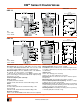
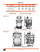


Volume litres (cubic inches)
Volume litres (cubic inches)
Size 12
Volume litres (cubic inches)
Volume litres (cubic inches)
Size 30
1. General
The design features of the DM
2®
Series D are of considerable
importance to users of double valves, such as on mechanical
power press applications and other critical applications. This
is because the DM
2®
Series D is designed to meet the latest
standards requiring “control reliable”, “Category-3 & -4”, or
“dynamic monitoring” capability.
Both the monitoring and memory capabilities of the DM
2®
Series
D valve are built in to the two piston-poppet stem assemblies.
During normal operation, the assemblies move between two
extreme positions. The 3rd, or intermediate, position occurs only
during valve lock-out. The valve will lock out whenever there is
sufficiently asynchronous motion between the two piston-poppet
stem assemblies. No additional external or internal devices
are needed to provide monitoring and memory. When the inlet
air supply is removed and re-applied, the valve “remembers”
whether it was in the ready-to-run or locked-out position prior
to the removal of the air supply. Resetting the valve after it has
gone in to “locked out” mode requires a momentary application
of a reset signal. Should the reset signal be inadvertently left on
(permanent signal), the valve will nevertheless go back in to lock-
out mode.
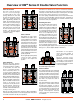
2. Description
The three way valve with DM
2®
capability consists of two main
valve systems and two pilot valve systems. The air flow paths
within the main valve systems are a proven combination of both
SERIES and PARALLEL paths.
Both pilot valves and both main valve elements are interconnected
with each other pneumatically. The main valve elements control the
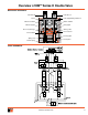
air via Crossflow™ air passages from inlet (port 1) to outlet (port 2).
Air flows first through a control element on one side of the valve
to a control element on the second side of the valve, hence a
series flow path. A parallel flow path starts on the second side
of the valve and flows to the first side of the valve. A total of four
elements control air flow from inlet to outlet. Air flow from outlet
(port 2) to exhaust port (port 3) occurs in parallel via the exhaust
poppets of both main valve elements.
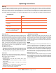
In normal operation, pilot air supply is maintained as long as the
two main elements operate in a synchronous manner. Whenever
there is asynchronous motion, however, one of the pilot air supplies
will be exhausted.
Sufficient pilot pressure is necessary to move the main valve
elements to their fully actuated or de-actuated positions.
Lack of sufficient pilot pressure will prevent a valve element from
fully shifting, resulting in the element stopping in the intermediate,
locked-out position.
3. Application
Uncontrolled movements of cylinders or rotary drives risks harm
to personnel and machinery. In order to reduce risk of injuries
and damage, pneumatic controls should ideally meet strict safety
requirements.
ROSS developed the DM
2®
Series D double valves for controlling
pneumatic clutch and brake mechanisms on mechanical power
presses. However, the features and functions built in to the
valve make it an ideal product to meet the specifications and
standards associated with other critical applications. Because
of its redundant design and the fact that the air is directed in a
Crossflow™ and SERPAR
®
pattern, the DM
2®
valve provides a
very high level of safety.
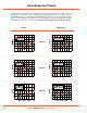
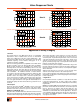
Application & Safety Category
Valve Response Charts
ExhaustingFilling
www.rosscontrols.com 11