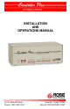
INSTALLATION AND OPERATIONS MANUAL 10707 Stancliff Road Phone: (281) 933-7673 Houston, Texas 77099 Internet: WWW.ROSE.
Limited Warranty ® Rose Electronics warrants the Caretaker Plus™ to be in good working order for one year from the date of purchase from Rose Electronics or an authorized dealer. Should this product fail to be in good working order at any time during this one-year warranty period, Rose Electronics will, at its option, repair or replace the Unit as set forth below. Repair parts and replacement units will be either reconditioned or new. All replaced parts become the property of Rose Electronics.
Table of Contents Contents Disclaimer .................................................................................................................... 1 Introduction .................................................................................................................. 1 Features ...................................................................................................................... 1 Model Number and Options ......................................................................
Introduction Disclaimer While every precaution has been taken in the preparation of this manual, the manufacturer assumes no responsibility for errors or omissions. Neither does the manufacturer assume any liability for damages resulting from the use of the information contained herein. The manufacturer reserves the right to change the specifications, functions, or circuitry of the product without notice.
Model Number and Options The Caretaker Plus consists of a switch unit and a separate wall mounted power adapter. It is available in several models: 2 to 8 ports, either serial or parallel, and Centronics tyhpe connectors or Db25 type connectors. The base model has a 16K buffer expandable to 2MB. The model number is described below. First Steps Contents You should have received the Caretaker Plus system unit, a power adapter, and this manual. Save the cardboard box and its polystyrene inserts.
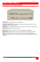
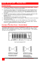
FRONT PANEL DISPLAY Caretaker Plus Front Panel Display POWER LED is lit whenever the unit is powered on. ADVANCE and SELECT switches are used to enter the configuration menu, go into diagnostic modes, or clear the buffer. MODE LED is lit to indicate the unit is in the configuration or flow control display mode. DATA LED lights as data is sent to the unit. BUSY LED is lit when the printer is on-line or busy while accepting data ERROR LED indicates an error has occurred, with LEDs 1-8 indicating which error.
QUICK SETUP LIST – Serial Units Serial Set-Up for PCs 1. 2. Connect your PC to port 1 on the Caretaker Plus with the proper cable. Connect the power adapter to the Caretaker Plus and turn the Caretaker Plus on. Verify that the power LED is on. The other LEDs light in various patterns as the power up tests are performed and then all go off. The ERROR LED will be lit for any errors. Run a communication program such as Procomm with the serial protocol set to 9600 baud, no-parity, 8 bits, and one stop bit.
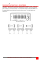
Caretaker Plus Rear Panel – Serial Model The diagram below shows the connector arrangement for model #CTP-8S. It has nine serial ports. The CTP-4S is similar but it doesn't have ports 5-8. Port 0, the rightmost port, is where you connect the printer. The computers connect to the ports labeled 1-8. the serial cables shown below are the most common ones. For other cables, see Appendix A.
QUICK SETUP LIST – Parallel Units Parallel Set-Up 1. Connect the Caretaker Plus port 0 to your printer with the correct cable. Connect your computers to ports 1-8 with the correct cables. Connect the power adapter to the Caretaker Plus and turn the Caretaker Plus on. Verify that the power LED is on. The other LEDs light in various patterns as the power up tests are performed and then all go off. The ERROR LED will be lit for any errors.
CABLING One of the most important steps in installing the Caretaker Plus is to connect the correct cables. We have tried to give as much information as possible to specify the correct cable. Please refer to Appendix A and B. Also refer to the previous section. Parallel Cabling Parallel units with Centronics connectors use standard IBM parallel cables to connect from PCs to the switch (port 1-8).
to indicate entry into configuration mode. Entering configuration mode will stop data transfer to the shared device, and also erase all data in the buffer. No new data can be loaded into the unit while in configuration mode. Press carriage return on your terminal to call the menu. The DATA LED will light indicating entry into the menu mode. You will be prompted for the proper responses. The configuration menu displays the setup parameters for all ports and allows you to change them.
Configuration Menu Items In the examples below, means "press the ENTER key", not "type the characters . Output from the Caretaker Plus is shown in courier type. Input from the user is shown in underlined courier type. Protocol The protocol consists of the baud rate, parity, word length, number of stop bits, and flow control. The factory default is 9600 baud, no parity, 8 bits, 1 stop, and DTR flow control. You may configure the protocol separately for each port.
Form Feed The form feed, when enabled, sends a form feed character to the shared device to eject the last page printed when a port is disconnected. The factory default is a disabled form feed. When enabled the last character sent to the shared device is examined. If it is a form feed no action is taken. If it is not a form feed, one is supplied. To change the form feed, enter F to the choice prompt, and answer Y or N to enable or disable the form feed. Enter choice (P,T,F,I,D.
Exit This command is used to exit the configuration menu and return the unit to normal (data transfer) mode. Enter X to the choice prompt. A termination message will print, and the BUSY, DATA, and MODE LEDs will return to the state they were in before entry to configuration mode. The unit is then ready to accept data. Enter choice (P.T,F,I,D,A,K.X, or H for help) X Configuration terminated Help (Main Menu) This option gives a brief description of what each command does. Enter choice (P,T,F,I.D.A.
Reverse Channel Data Timeout This command (on the advanced features menu) determines whether or not to reset the timeout clock when data is received on port O "reverse channel data". When this feature is enabled, reverse channel data resets the timeout clock. When this feature is disabled, reverse channel data does not reset the timeout clock. Because some printers, particularly the HP LaserJet.
Configuration Commands Configuration commands allow changing of the unit's setup parameters without the Use of a menu. They may be used on serial or parallel units. To enable processing of configuration commands, depress both of the unit's front panel switches. The MODE and BUSY LEDs will light. This indicates that the unit is in configuration mode. The unit must be in this mode to process configuration commands. To leave the configuration mode, depress both switches again.
Protocol Command This command changes the communication protocol of a given port. If you enter a protocol that blocks communication with the unit or is otherwise undesirable, and you have not used KEEP, you may restore the previous format by powering the unit down and back up. Protocol codes differ for serial and parallel models. In the parallel models only port 0 has a changeable protocol. In the serial models any port may be changed.
Parallel Enable Logic Command This command allows the Caretaker Plus to recognize when a computer that is connected to a parallel port on the Caretaker Plus is turned off so that the Caretaker Plus will not accept data from the PC. The factory default is to enable parallel enable logic. When this feature is enabled, the Caretaker Plus requires the INIT line to be high and the SELECT line to be low before receiving any data from the port. If a character other than Y or N is used no action is taken.
OPERATIONS Initial State Following the successful completion of the power up tests, the Caretaker Plus turns all the port LEDs off. The BUSY LED may be lit if the shared device is busy. Normal Operation Input devices, usually computers, initiate requests to connect to the shared device by sending data to the Caretaker Plus. If no other ports are currently connected, connection with the shared device is made immediately.
Buffer Characteristics The switch may have a buffer memory of 16K, 256K, 512K, 1 megabyte, or 2 megabytes. The Caretaker Plus uses an intelligent algorithm to allocate memory. The buffer is dynamically allocated which means that any port can utilize as much buffer as required. The buffer is reclaimed to be used again as the data in the buffer is sent to its destination. As the memory becomes full, the reclaimed memory is first distributed to a currently active port, then to the queued ports as needed.
Timeout The default setting of 20 seconds is sufficient for most applications. Some computers, however, start printing and then pause to do some type of calculation or processing and then resume printing. If this pause is greater than the timeout setting of the switch. then another computer could start printing and possibly interrupt the printing of the first job and ruin its printout. In this case, it is necessary to increase the value of the timeout through the configuration process.
Initialization String The initialization string is used to reset the printer to a defined state at the beginning of each job. In this way the printer settings of the last person to print do not affect the print settings of the next person to print. The most common string used is the reset command in the printer. The reset sequence for HP laser printers is ESC E. For Epson printers the reset sequence is ESC O.
Power Up Initial Display When powering on, the Caretaker Plus goes through a power up self-test which checks the main functions of its electronics. The leftmost LED labeled POWER should glow green and the other red LEDs should all turn on. Then the unit will cycle through four tests lighting up LEDs 1 through 4 as each test is performed. Errors are indicated by the ERROR LED lighting and the unit halting. See TABLE 6 for the full sequence of the power up LED display and TABLE 7 for error displays. Table 6.
Static Ram Read/Write Test The next test is for static ram. Since the Caretaker Plus has no static ram, this test is displayed as shown in TABLE 6 for consistency with other Rose products. Non-volatile Ram Tests The fourth and final power up test is for the non-volatile memory. A series of tests are performed. An error shown by the LEDs as error 4 indicates that the data in the nonvolatile memory has been corrupted. To attempt to rewrite the default parameters push SELECT switch then the ADVANCE switch.
Flow Control Display Mode (Serial Models Only) By pressing the ADVANCE switch during normal operation, the LED display is switched to the flow control display mode. The MODE LED illuminates to indicate this mode is active. You may return to normal display mode by pressing the ADVANCE switch again. During flow control display mode, the corresponding port LEDs light only when the Caretaker Plus has instructed the connected device to stop sending data via the port's currently selected protocol.
TROUBLESHOOTING Troubleshooting Common Problems and Solutions I. Missing blocks of data on shared device and/or buffer Overflow error display occurs - serial only A. Flow control is not set or wired properly If your device uses X-on/X-off, ensure that the corresponding port is set for X-on/X-off. If you are using DTR you have a miswired cable, see Section IIA below. II. Nothing happens when sending data A. Improper cabling See 'CABLING' section. B.
V. Port(s) do not time out A. 'Robust' X-on/X-off present. Some printers, particularly the HP LaserJet, send X-on codes at timed intervals. Set the 'REVERSE CHANNEL DATA TIMEOUT' feature to Y. See 'CONFIGURATION' section for information on 'REVERSE CHANNEL DATA TIMEOUT'. Other options are disconnect pin 3 on port O, configure the printer for normal X-on/X-off, or configure port O to X-on/X-off. B. Improper wiring A computer which is powered off is making a port busy.
Maintenance and Repair The exterior surface of the unit may be wiped with a damp cloth to keep it clean. The unit does not contain any jumpers or serviceable parts inside. Opening the unit invalidates the warranty except in the case of an authorized memory upgrade or firmware updates. Any malfunction of the unit should be reported to a factory authorized repair center for service.
DIAGNOSTICS Diagnostic Modes The Caretaker Plus has an extensive self-test diagnostic capability. Normally these features are only accessed by a technician to determine a failure with the unit. Through the diagnostic modes, you can: Print the configuration menu Print a repeating test pattern on the printer Restore the non-volatile memory to its factory defaults Test the EPROM, buffer memory, and non-volatile memory Test all signals on each I/O port There are three diagnostic modes that can be entered. 1.
Print Configuration/Test Pattern Function Holding both switches down at the end of test 4 causes the unit to print its configuration out to port O, as shown in TABLE 8. Holding both switches down a second time at the end of test 4 causes a print exerciser to run, which sends a repeating test pattern out to the device on port O. To stop the exerciser, press both switches again. The exerciser may be started and stopped again the same way. The exerciser follows the protocol assigned to port O.
DIAGNOSTICS Long Test Without Loopback This group of tests are entered by pressing the select switch only while powering up the unit with the on/off switch. All equipment should be disconnected from the unit prior to running this test. Test 1 - EPROM program checksum test is the same as described previously. Test 2 - Dynamic ram test checks the dynamic ram more extensively than the short test or the power up test. The test takes longer to perform.
Long Test with Loopback This test is entered by pressing the advance switch only while powering up the unit with the on/off switch. Special loopback connectors should be connected to each Caretaker Plus port. Tests 1-5 - These are the same as tests 1-5 of long test without loopback. Test 6 - The loopback test assures that all port signals are functional. In order for this test to pass, special loopback connectors must be installed on each port, see TABLE 9.
APPENDICES Appendix A: Serial Cabling The diagrams below show the Caretaker Plus pinout on the left and all other devices on the right. Read across to find the pinout. Connector types shown below refer to the connector on the device, not on the cable. NOTE: Caretaker Plus is abbreviated CTP.
Appendix B: Pinout Specifications DB25 Female Serial Models Pin Signal Name Acronym I/O Description 2 Transmit data TXD Output Serial data from port 3 Receive data RXD Input Serial data to port 4 Request to send RTS Output Always high 6 Data set ready DSR Input Low inhibits transmit data 7 Signal ground GND Common 20 Terminal ready DTR output Pin 20 is the hardware flow control output. Pin 6 is the hardware flow control input. Pin 6 has an internal pull-up to set it high when no signal is connected.
Appendix C: MP1000 Memory Board This memory board provides optional, add-on buffer expansion for the Caretaker Plus. Installing this board expands the Caretaker Plus buffer from the standard 64K to 256K, 512K, or 1 MB. "Stacking" two boards allows the buffer to be increased to 2 MB. This card requires the use of 256K x 4 DRAM chips (standard 20-pin DIP type; the speed doesn't matter). About the Board This unit consists of a socketed printed circuit board, with spaces for eight DRAM chips.
Installing the Board Carefully plug the expansion pins of the board (the first board, if using two) onto the motherboard's sockets where the 64K chips were removed. Fasten the board down using the two threaded spacers. Screw them into the motherboard's existing spacers (after removing two small Philips-head screws that may be in place). The spacers should be finger-tight. If using two boards, stack them by plugging the expansion pins of one into the expansion sockets of another.
Appendix D: Factory Defaults Upon receiving the Caretaker Plus from the factory, or restoring the unit to default parameters (see 'RESTORE TO DEFAULT FUNCTION'), The factory default settings are: Timeout: 20 seconds Protocol Serial: 9600 baud, no parity, 8 bits, 1 stop, DTR flow control Protocol Parallel: Use busy and acknowledge Form Feed: Off Initialization String: None Unidirectional X-on/X-off: Yes Parallel Enable Logic: Yes Reverse Channel Data Timeout: No Flow Timeout on Busy (Ports 1-8): Yes Filter S
10707 Stancliff Road Houston, Texas 77099 Phone: (281) 933-7673 WWW.ROSE.