SWING CHAIR ASSEMBLY MANUAL
I ASEEMBLY INSTUCTION BEFORE ASSEMBLING.MAKE SURE THAT YOU LAY OUT AND IDENTIFY ALL PARTS LISTED BELOW IN THE PARTS LIST. INSTALL ON LEVEL GROUND. INSTALL NOT LESS THAN 6 FEET FROM .A NY OBSTRUCTION SUCH AS FENCE, GARAGE,HOUSE, OVERHANGING BRANCHES, LAUNDRY LINES.OR ELECTRICAL WIRES. TIGHTEN ALL NUTS AND BOLTS SECURELY.ALL BOLTS SHOULD BE HAND TIGHENED BEFORE USE.NEVER USE POWER TOOLS OR EXCESSIVE FORCE DURING ASSEMBLY AND TIGHTENING OF BOLTS.
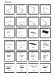
Part list LEG TUBE AX2 "- -, LEG TUBE TOP CROSS BAR BX2 CX1 LEG CROSS HANGING PIPE EX2 E1X4 SPRING HOOK � HX2 CANOPY TUBE .... ARMRES T r IX2 $ ::-- KX2 LX2 BOLT BOLT QX2 BOLT BOLT Ullil l' :;;X24 � TX2 1·::;�32 NX2 BACK LEG CROSS BACK LEG CROS! FX1 GX1 SEAT FRAME BACK FRAME J1X1 .........
Part list NUT � WASHER M6X15 M8X8 w ALLEN KEY M6X15 @) M8X8 X WRENCH PLASTIC SCREW � YX2 PLASTIC END CAP g z M6X15 M8X8
STEP -1 Connect part D and part C to build the beam using bolt Q washer X,nut Wand plastic end-cap Z as shown in diagram. I I / I I \ --. - ----- I 1.,,, - I I ....... \ \ \ \ \ \ // --_jjj ', \ Q r-y--' I \ \ \ -----STEP-2 Connect part A and part B with beam using bolt U washer X,nut Wand plastic end-cap Z as shown in diagram. --- - .... _ ,, / I /,I I I I I ' ' -- ....___ ,,,� \ B Attention:Both part A should be the sime side.and both part B should be in the other side.
STEP-3 Connect part E and legs (part A&B) using bolt R washer X,nut Wand plastic end-cap Z as shown in diagram. '' '' \ I I R l--'\--�J I I I / STEP-4 / Connect part G and part F to build a connection tube for the rear foot using bolt O,washer X,nut W and plastic end-cap Z as shown in diagram.
STEP-5 Connect the rear foot tube with part B using bolt S washer X,nut Wand plastic end-cap Z as shown in diagram. 0 - STEP -6 Set up seat&back together 1.Connect part J1 and part J together using bolt N,washer X,nut Wand plastic end-cap Z as shown in '\diagram. // z 2.Connect part I and part J using bolt T washer X,nut Wand plasticend-cap Z as shown in diagram.
STEP -7 1.Connect part E1 with backseat (part J1 )using bolt V,washer X,nut Wand plastic end-cap Z as shown in diagram. 1 2. Connect part E1 to armrest (part I) using bolt P,washer X,nut Wand plastic end-cap Z as shown in diagram. STEP-8 Use part H to hook the seat to the frame.
STEP-9 STEP -10 Affix part K to beam using screw Y. Insert part L to canopy.
STEP -11 Connect Part L and Part K to support canopy.