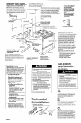
A l l l l WARNING ALL RANGES,CAN TIP lNJURY.TO PERSONS COULD RESU,LT INSTALLANTI-TIP DEVICE’PACKED WITH RANGE 3EE’INSTALLATION INSiRUCTlONS IMPORTAiVT: Read and save these in&,rktionS. 0.36-303601-02-01 4320751Rev. B IMPORTANT: Installer: Leave Instdlation Instructions with the homeowner., Homeowner: Keep Installation Instructions for future reference. SaveInstallation Instructions for local electrical inspector’s use.
Before you start... Proper hlstallanon is your responsibility. A qualified technician should ihstall this range. Make sure you have everything necessary for correct installation. It is the responsibility of the installer to comply with the installation clearances specified on the serial/rating plate. The serial/rating plate is located under the ranae moktor~. ALL OPENINGS IN THE WALL OR FLOOR WHERE THE RANGE IS TO BE INSTALLED MUST BE SEALED. “‘Note: l/C flame retardaM m.
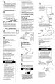
D. A 120-volt, 60-Hz, AC-only, 15-ampere, fused electrical supply is required. A time-delay fuse or circuit breaker is recommended. It is recommended that a separate circuit serving only this appliance be provided. Electronic ignition systems operate within wide voltage limits, but proper grounding and polarity are necessary.
_- Electronic Ignition System. Initial 13 . Place rack in oven. Place level on rack, first side to side; then front to back. If range is not level, pull the range forward until the rear leveling leg is removed from bracket. Adjust the legs up or down until the range is level. Push range back into position. Check that range leveling leg is engaged in bracket. 8 Note: Oven must be level for satisfactory baking conditions. n Line up holes in anti-tip bracket with holes in floor.
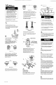
Check the oven burner for proper flame. This flame should be l/2” long, with inner cone of bluish-green, and outer mantle of dark blue, and should be clean and soft in character. No yellow tips, blowing or lifting of flame should occur. shutter until the proper flame appears. Tighten screw. Replace oven bottom, oven racks, and storaae drawer. Countertop preparation: If side trim kit is used, you may need to do the following.
-...- --- - n$-----Cap -----A+ -L!%K-msen 7lfsl-- - L.P. gas . conversion Ficmre 7 3. Remove the cap with screwdriver slot. Remove the black insert marked “NAT.’ from the cap (the insert fits very tightly). Reverse the insert and push it firmly back into the cap. The marking ‘L.P.’ should appear on the insert. Be sure the insert is pressed into the shoulder. Do Not disturb the spring in the body of the regulator. Replace the cap in the body of the regulator and tighten. See Figure 7. Converting to L.
If range does not operate... . Check that the circuit breaker is not tripped or the house fuse blown. . Check that the power supply cord is plugged into wall receptacle. . Check that the gas supply is turned on. If vou need a&stance... The Roper Consumer Assistance Center will answer any questions about operating or maintaining your range not covered in the Installation Instructions. The Roper Consumer Assistance Center is open 24 hours a day, 7 days a week. Just dial l-(800) 4476737 -the call is free.