Sep/2019 INSTALLATION MANUAL RT – Roof Entry Bracket Contents ・INTRODUCTION ---------------------------------------------1 ・Tools & Supplies Required for Assembly ---------------2 ・INSTALLATION SAFETY ----------------------------------2 PART A: Materials -----------------------------------------------3 PART B: Installation Condition -------------------------------5 PART C: Installation -------------------------------------------7 PART D: Appendix (Grounding) ------------------------------18 10620 Treena
Introduction Introduction Please review this manual thoroughly before installing your Roof-Tech system. Aside from reading this manual. This manual provides supporting documentation for the installation of Roof-Tech’s Roof Entry Bracket products. We recommend installer to carefully review the instructions provided by the PV module manufacturer and become acquainted with OSHA’s safety procedures prior to installing the PV system.
Installation Safety Tools & Supplies Required for Assembly Tools needed for building the array ・Hex wrench bit socket (8 mm) ・Holesaw(φ45mm、φ1-3/4 inch) ・Drill andφ3 mm Drill Bit for sheet metal (for Installation on Metal Roof) ・Measuring tape ・Marker pen ・Torque wrench ・Scissors Item 4.0x16 Screw 5.0x60 Wood Screw Torque 1.
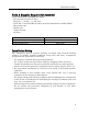
Materials PART A: Materials 1. ① ② ③ ④ ⑤ ⑥ Items with RT-Roof Entry Bracket Item Roof Entry Bracket Base Roof Entry Bracket Cover Screw M4×16 Star washer M4 Wood Screw 5.
Materials Roof sealant ⑫ Item Roof sealant ※Recommended Product ・Henry : 208R, 209, 925 (Black) ・Geocel:S2, S4 (Black) ・Sashco : Through the Roof ・Boss : 125 (Black) ・Top Industrial: Rain Buster 850, 900 ・Chem Link: M1 ・NPC Solar Seal 900 ・GE All Purpose 100% Silicone ⑫ 4
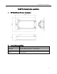
Installation condition PART B: Installation condition 1. RT-Roof Entry Bracket dimension 2.
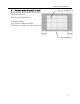
Installation condition 3. Feasible area to install on roof RT-Roof Entry Bracket shall be installed above the roof attic. Ex; Pipe, Ventilation etc.
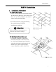
Installation PART C: Installation 1. Installation of Brackets (1) Inspect the location ① Once you find where you want to install RT- Roof Entry Bracket, please make sure there are no cables, lights or any objects under roofing and sheading. ② Location must be selected following the condition from PART B, installation condition. ! Attention Hole location Follow installation requirements to avoid the risk of water leakage.
Installation ■Hole-sawφ45mm ② Cutting out roofing and deck. Use φ1 3/4 inch (φ45mm) Hole saw (φ1 3/4”) to cut out penetration hole. ! Attention Hole-saw shall be φ1 3/4” (φ45mm) ■center hole ③ Use blower to clean roof surface. ■Blower ■Roofing ④ Remove one side cover paper from Butyl for roof entry hole.
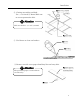
Installation ⑤ Tape the butyl tape around the entry hole on roof. The butyl tape must expose 3/8 inch (10mm) above the roof surface. The butyl tape adheres to the inside of the hole. ■Butyl with Protective paper (Inside) ■Butyl tape for roof entry ⑥ Overlap 1/8 inch (3mm) and cut off the extra butyl tape. ■Cut off the extra part of butyl tape ■Tape shall be started to install from right corner. And over wrap 1/8 inch. ⑦ Make a cut in 4 location as it is shown.
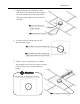
Installation ⑧ Remove all protective paper from Butyl tape and fold it around the surface. Apply pressure on the Butyl tape to adhere to the roofing surface. ! Attention All paper to be removed. ■Round hole cap ⑨ Install Round hole cap. Put good pressure to Round hole cap to seal tight. ⑩ Trim the exposed butyl tape off. ! Attention The hole cap has a tight fit with the entry hole of the bracket. It is very important to cut extra butyl tape out around the cap.
Installation ⑪ The butyl spacer can be used to fill the gaps under the surface where it is installed. If there is a gap under the base, fill it with butyl spacer, and use sealant to seal between the upper shingle edge and the lower shingle surface. ■Butyl Spacer ■sealant [Multiple shingle layers] If there isn’t a flat surface or space to install the RT-Roof entry bracket, the following PART B in this manual illustrates the cutting of the roof shingle “teeth” layer to create the mounting area.
Installation ⑫ If there is a gap within 1 3/16 inch (30mm), use butyl spacer to fill it. ■Butyl Spacer ■Butyl Spacer ⑬ Remove the protective paper from under the base of the bracket. ! Attention Please make sure all paper should be clearly removed.
Installation ⑭ Locate the installing surface and place the Roof Entry Bracket. ■Roof Entry Bracket base ⑮ Install and secure Base with 3 screws ■Wood screw 5.0x60 (Wood Screws 5.0×60(W/P) ! Attention Make sure base is tightly sealed to the roof surface. No gaps underneath it. ! Attention Note: Proper torque values for the 5.0×60 mm screw will vary depending on the rafter and/or deck characteristics; hardness, age, and moisture of the wood. Tightend until the washer just stop rotating easily.
Installation (3) Wire management ① Install Conduit Fitting to base which is the eave side of base wall.
Installation ② Push the wires through the bracket.
Installation ③ Once all the wires are installed, the entry hole shall be filled with the sealing putty. The sealing putty will prevent all moisture and dust from getting inside of the roof. ■Sealing putty ■Sealing putty Point Sealing putty can be installed in 3 steps. (1) Fill the sealing putty from the ridge side of the hole. (2) Fill the edge side and under the wires. (3) Place the rest of the putty on top of the wires to cover.
Installation (4) Install Roof Entry Bracket Cover ① Roof Entry Bracket Cover is installed ■Screw M4×16 once all wiring or cable installation is finished. Use the 3 Screw M4×16 with Star washer ■Star washer M44 provided to secure the cap. ! Attention Screw M4x16 must be installed hand tight, do not use drills or any electrical tools. ■Roof Entry Bracket cover (5) Apply the sealant around the base ① Seal around the base after the cover is installed. Sealant shall be installed side and ridge side only.
Grounding PART D: Appendix (1) Ground Wire installation ① Install Grounding Lug to the base. (Grounding Lug and screw are not included) ■Screw for Grounding Lug ■Grounding Lug ② Set the Grounding Wire through the round opening.
Grounding ③ Use Grounding lug to fix grounding wire. ■Lug ■Ground Wire ④ Go back to P.15 (2) Grounding Setup All electrical installation and procedures should be conducted by skilled, licensed and bonded electricians. Installer is responsible for and shall provide an appropriate method of direct-to-earth grounding in accordance with the latest edition of the Canadian Electrical Code Part 1, CSA 22.