Jan/2021 INSTALLATION MANUAL RT-MINI Contents ・INTRODUCTION ---------------------------------------------1 ・PERIODICAL INSPECTION ------------------------------2 ・Tools Required for Assembly ・INSTALLATION SAFETY ------------------------------2 ----------------------------------3 PART A: Materials ------------------------------------------------4 PART B: Bracket Installation ---------------------------------5 ADDENDUM: Metal Roof Installation -------------------17 ADDENDUM: Classic rib Metal Roof Instal
INSTALLATION MANUAL Contents ・Introduction ------------------------------------------------------------1 ・Periodical Inspection ------------------------------------------------2 ・Tools Required for Assembly -------------------------------------2 ・Installation Safety ----------------------------------------------------3 PART A: Materials ----------------------------------------------------------4 PART B: Bracket Installation -------------------------------------------5 1.
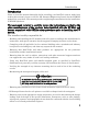
Introduction Introduction Please review this manual thoroughly before installing your Roof-Tech system. Aside from reading this manual, please review the P.E. Stamped Engineering Letters for the RT-MINI products for your State. This manual provides supporting documentation for the installation of RT-MINI products.
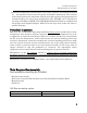
Periodical Inspection Tools Required for Assembly ・Roof Tech recommends a thermal splice every 14 Ft., however, it must be determined by the installer based on the rail system installation instructions. The installer must also determine the maximum allowed span and cantilever design parameters recommended by the rail system manufacturer. The RT-MINI can be installed on low slope roofs (Metal, EPDM, TPO, SBS Modified Bitumen/Torch-on, Asphalt) and steep slope roofs (Asphalt shingles, Metal).
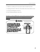
Safety Technical Note Proper torque values for a wood screw will vary depending on the rafter and/or deck characteristics; hardness, age, and moisture of the wood. Tighten the M5x60mm wood screws until the conical washer stop rotating. Stainless hardware is soft and if dry torqued too quickly it may cause the nut and bolt to seize. Roof Tech recommends all stainless steel threads be lubricated.
Safety Installation Safety The installation process requires working on sloped and elevated building surfaces, in outdoor weather conditions, using tools and heavy components designed for the generation of electricity. ・ Use properly anchored fall protection equipment. ・ Use caution to prevent objects from falling or dropping off the roof area. ・ Cordon off ground areas directly beneath the roof work area when possible. ・ Always use personal protection equipment such as safety glasses, gloves, etc.
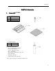
Materials PART A: Materials 1. Items with RT-MINI ① RT-MINI Bracket Set 1A 1B 1C Item RT-MINI Screw 5.
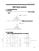
Bracket Installation PART B: Bracket Installation 1. Installation of Brackets (1) Bolt options a) For the 5/16” or M8 hex bolt, use the lower channel. (L-Foot mounting option) b) For the ¼” hex bolt, use upper channel. (EMT clamp mounting option) Note: M6 hex bolt will not fit the RT-MINI base. (2) Brackets Layout There is 1 9/16 inch (40mm) adjustability to secure the bolt.
Bracket Installation ① Locate and place MINI base on the cross section of chalk line. ② Protecting the edge of the shingles. Note: The MINI base is structurally engineered to be mounted on the above position (structural). However if used for accessories such as junction boxes or EMT with no structural value, It can then be mounted on any orientation.
Bracket Installation ③ Chalk line according to the layout plans to indicate bracket’s position. ④ Aligning the brackets. Choose the most suitable rafter, then mark the center. (ⅰ) Line M: Vertical Bracket center line. (ⅱ) Line Y: Horizontal Bracket center line. The Engineer of Record (EOR) shall verify the framing capacity and fastener installation for building code compliance including those of the National Design Specification for Wood Construction (NDS 2005/2012/2015) as applicable.
Bracket Installation (3) Bracket Installation ! Attention To maintain the flashing performance, avoid installation when the temperature is below 22F or above 176F. RT Butyl must be installed on a dry surface. ① Mark the location at the intersection of the Y Line and M Line. ! Attention Minimum clearance between mounting screws and the edge of the roofing shingle shall be 3/8 inch (10 mm). In case the stainless screw hit the nail underneath the shingle; 1) Tip the driver at an angle.
Bracket Installation ② Adjust the RT butyl tape to match the height of the upper shingle. When there is a gap, a slit, or a height difference at the mounting location of the bracket, use additional RT butyl tape. ● When there is a slit at the installation spot, fill in with the additional RT butyl tape. The slit must be filled with RT butyl tape. ● When there is a slit above the bracket, fill it in with RT butyl tape to match its shape. Apply roof sealant around the RT butyl tape.
Bracket Installation Rafter or Deck Install ③ If there is a shingle gap within 2 inches from the base, sealant shall be applied to the gap as it is shown. ● Best to position bracket 2 the inches away from the slit. ● If the mounting screw is within less than 2 inches from the slit, fill the slit with roof sealant.
Bracket Installation [Case 1] ● Use RT butyl tape to level the surface of shingle roof. the Cut " t eet h" wher e br acket shal l i nst al l composite ¡ But yl spacer ¡ But Butylyl spacer spacer ¡ ¡ But yl spacer ¡ But yl spacer Fl ush wi t h shi ngl e Not e: Do not spl i ce t he but yl t ape. Not e: Do not spl i ce t he but yl t ape.
Bracket Installation [Case 2] ¡ But yl spacer ● Building layers of RT butyl for the bracket to be mounted over the teeth region of composite shingle roofs. We recommend maximum. 4 layers Layer 1 is already applied to the bottom of the bracket. ¡ But yl spacer The following layers must be cut to shape to cover the surface of the bracket at each location, assuring a leveled surface.
Bracket Installation [Case 3] ● Roofing Leveling Option The application of one layer of asphalt roofing shim with the proper asphalt roofing cement is an alternative to leveling when a Roof Tech base is to be installed between 2 levels (layers of asphalt shingles). The Roof Tech Structural Stamped letters are prepared based on 2 layers of shingles. ④ Peel off the protective paper from the RT butyl tape.
Bracket Installation ⑤ Installing the bracket. [Fastening it to the Rafter] Place the brackets at the specified position and make sure the RT butyl makes good contact with the roofing surface. Slide the M8 or 5/16” Hex bolt into place before fastening the bracket on the roof. Set the bracket with 2 ea. Screws, M 5.0 × 60 mm stainless wood screw using 8 mm hex socket. After completing process, make sure the brackets are securely fixed.
Bracket Installation [Fastening it to the Roof Deck] ! Attention When the MINI base is installed on the deck, 5 screws must be used. Four screws are fixed into the sides and 1 on the ridge side. Note; Each MINI is shipped with 2 mounting screws. The installer must purchase additional screws when mounting it to the roof deck. ! Attention Note: Proper torque values for the 5.0×60 mm screw will vary depending on the rafter and/or deck characteristics; hardness, age, and moisture of the wood.
Bracket Installation ⑥ Apply roof sealant to the top and each side edge of the brackets. This adds additional UV protection. Cover the exposed RT butyl tape with roof sealant. No need to apply it to the bottom of the brackets. ! Attention You may verify that the screws underneath the deck panel are stained with butyl rubber. This indicates a good flashing performance. the deck panel are stained with butyl rubber.
ADDENDUM Installation Instruction for Metal Roofing Installation on a Metal Roofing 1. Requirement ・ Applicable to maximum 20 gage metal decking. ・ The roof should have sheathing (deck) board and the metal roofing should be flat and flush against the sheathing board at least 4 1/4 inch (108mm) by 4 3/4 inch (120mm) area at the bracket mounting location. The Roof Tech P.E. Letters are created for a minimum 7/16” OSB with 2x4” rafters 24 in o.c.
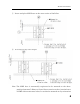
ADDENDUM Installation Instruction for Metal Roofing 2. Marking on the Roof (1) Layout [Fastening to the Rafter] ① Mark at ±35 mm from the intersection of the M Line and Y Line on the M Line. (See illustrations.) ② In case of Deck Installation, mark at ±15 mm, ±25 mm from the intersection of the M Line and Y Line. ③ Then mark at ± 32.5 mm [Fastening to the Deck] from the M Line ④ Mark at +35 mm from the Y Line on the M Line.
ADDENDUM Installation Instruction for Metal Roofing 3. Bracket Installation ① Drill the roofing metal sheet with a φ1/8 inch (φ3 mm) drill bit at the markings. [Fastening it to the Rafter] [Fastening it to the Roof Deck ] ! Attention Be careful to minimize the intrusion of the drill bit into the sheathing board. ② Deburr the edges and fill the drilled hole with roof sealant.
ADDENDUM Installation Instruction for Metal Roofing ③ Peel off the protective paper from the RT butyl tape. ! Attention Do not leave any protective paper on the surface of the RT butyl tape, it can cause an improper seal and may allow water intrusion under the bracket. ④ Place the brackets at the specified location and make sure the RT butyl attaches well to the roofing surface. Set the bracket with 2 ea. (for RAFTER), or 5 ea. (for Roof DECK), of 5.
ADDENDUM Installation Instruction for Classic rib metal roofing ⑤ Apply roof sealant around the brackets, the top and each side edge of the brackets. Cover the exposed RT butyl tape with roof sealant. Do not apply sealant to the bottom of the brackets.
ADDENDUM Installation Instruction for Classic rib metal roofing Installation on a Classic rib metal roofing 1. Requirement ・ The Roof Tech P.E. Letters are created for a minimum 7/16” OSB with 2x4” rafters 24 in o.c.
ADDENDUM Installation Instruction for Classic rib metal roofing 2. Marking on the Roof (1) Layout ① The MINI base must be mounted on the flat surface. Please make sure the location is not on slope surface of metal ribs. ② In case of Deck Installation, mark at ± 15 mm, ± 25 mm from the intersection of the M Line and Y Line. [Fastening to the Deck] ③ Then mark at ± 32.5 mm from the M Line ④ Mark at +35 mm from the Y Line on the M Line.
ADDENDUM Installation Instruction for Classic rib metal roofing 3. Bracket Installation ① Drill the roofing metal sheet with a φ1/8 inch (φ3 mm) drill bit at the markings. [Fastening it to the Roof Deck ] ! Attention Be careful to minimize the intrusion of the drill bit into the sheathing board. ② Deburr the edges and fill the drilled hole with roof sealant.
ADDENDUM Installation Instruction for Classic rib metal roofing ③ Please add a butyl pad (RT Butyl Spacer) on the surface between the ridges. ④ Peel off the protective paper from the RT butyl tape. ! Attention Do not leave any protective paper on the surface of the RT butyl tape, it can cause an improper seal and may allow water intrusion under the bracket. ⑤ Place the brackets at the specified location and make sure the RT butyl attaches well to the roofing surface.
ADDENDUM Installation Instruction for Classic rib metal roofing ⑥ Set the bracket with 5 ea. (for Roof DECK), of 5.0 × 60 mm stainless wood screw using 8 mm socket. After completing process, make sure the brackets are securely fixed. ! Attention When the MINI base is installed on the deck, 5 screws must be used. The screws are fixed into the side 4 holes and 1 ridge side hole. Note; Each MINI is shipped with 2 mounting screws.
ADDENDUM Installation Instruction for Classic rib metal roofing ⑦ Apply roof sealant around the brackets, the top and each side edge of the brackets. In addition, please fill and form a slope and triangle at the ridge side. Cover the exposed RT butyl tape with roof sealant. Do not apply sealant to the bottom of the brackets.
ADDENDUM MINI used with L-Foot and Rail It is important that the designer and installer are acquainted with the PE stamped letters posted on http://www.roof-tech.us/support.
ADDENDUM MINI used with L-Foot and Rail 30
Customer Support For assistance: call Roof-Tech customer support. (858) 935-6064 http://roof-tech.