
Install Manual


Electrical Setup
64
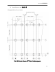
3. Bonding Path Diagrams
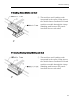
A: Bonding Middle Clamp
① The stainless steel bonding teeth
integrated in the Middle Clamp pierces
the module frame anodization to bond
module to module through the clamp.
(Bonding path between PV panels)
② The toothed washer bonds the
aluminum Middle Clamp to the
stainless steel head cap screw,
removing the clamp anodization.
③ The head cap screw thread creates the
bonding path to the U-D Bracket.
B: Bonding End Clamp
① The stainless steel bonding teeth
integrated in the end clamp pierces the
module frame anodization to bond
module to clamp.
② The toothed washer bonds the
aluminum end clamp to the stainless
steel head cap screw, removing the
clamp anodization.
③ The head cap screw thread creates the
bonding path to the U-D Bracket.
A
B