
Install Manual
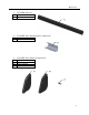
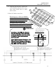

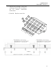

LANDSCAPE
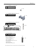
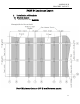
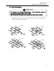
BRACKET LAYOUT
12
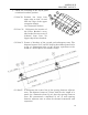
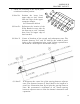
① Chalk line according to the layout plans
to indicate bracket’s position.
(i) Line Y0: Position the lower base
upper edge at 3/16” (5 mm)
from the edge of the upper
composite shingle.
(see illustration bellow)
(ii) Line Y1: Delineates the location of
the Pillar Bracket’s eaves
side for the first row at 4-1/8”
(105mm) from Line Y0
(upper edge of base bracket).
(iii) Line Y: Center of brackets of the second and subsequent rows. The
distance between Y1-Y and Y-Y shall be the width of panel (refer
to Pg. 11 illustration) plus 1-1/16” (27mm, equivalent to the
width of a Panel Spacer and middle clamp).
(iv) Line T: It delineates the center line of the spacing between adjacent
rows. The distance between T Lines shall be the length of a
panel (see illustration from Pg.11) plus the spacing between
rows. We recommend a minimum of 1/8” (3 mm) spacing
between adjacent rows to allow for thermal contraction and
expansion.
Y
Y0
Y1
Y0
Y1
T
T
T
T
T
Y
Y
Y