May.
Contents ・Introduction ------------------------------------------------------------1 ・System Fire Ratings -------------------------------------------------2 ・Bonding/Grounding of Modules ----------------------------------2 ・Periodic Inspection --------------------------------------------------2 ・Tools & Supplies Required for Assembly -----------------------3 ・Moisture Content ----------------------------------------------------4 ・Installation Safety ----------------------------------------------------4 ・Dis
PART D: Portrait Layout 1. Installation of Brackets (1) Bracket Layout a) Rafter Installation b) Deck Installation PART E: Electrical Setup ----------------------------------------------56 ----------------------------------------56 -----------------------------------------58 ----------------------------------------------61 1. Cable Management Options ------------------------------------61 2. Grounding Setup ---------------------------------------------------62 3.
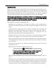
Introduction Introduction Please review this manual thoroughly before installing your Roof-Tech system. Aside from reading this manual, please review the PE Stamped Engineering Certification for the Roof-Tech APEX Solar products for your State. The Roof Tech Structural Stamped letters are prepared based on 2 layers of asphalt shingles. This manual provides supporting documentation for RT-APEX.
Introduction System Fire Ratings Roof Slope Module*1 Skirt (Wind Deflector) Fire Rating*2 Steep Slope Type 1 & 2 - Class A (≥2/12) Low Slope Type 1&2 Required Class A (<2/12) *1: Module Type per UL 1703 (November 18, 2014). *2: Class A fire rated PV systems can be installed on Class A, B, and C roofs.
Tools & Supplies Required for Assembly Tools & Supplies Required for Assembly Tools needed for building the array ・Hex socket drive 8 mm (for the base) ・Hex socket drive 7 mm (for the Screw M4x16 SDST) ・Hex bit socket long 8 mm (for the Clamps and Pillar) ・Phillips head screwdriver bit (for the Tapping Screw M4x16) ・Drill andφ3 mm Drill Bit or Center punch for sheet metal (for Installation on Metal Roof) ・Measuring tape ・Chalk line ・Torque wrench ・Scissors Torque Values for Dry Bolts: 16 N・m applied to Mid
Installation Safety Moisture Content RT Butyl Flexible Flashing is to be installed on dry mounting surfaces. Determining how wet is too wet: First, remove the paper backing from an RT product exposing the clean RT Butyl. Second, press the base, RT Butyl side down against the surface. Third, pick up the base. If the base adheres to the roof, the roof is suitably dry for installation.
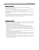
Distance from roof to bottom of PV module Distance from roof to bottom of PV module In case of 40mm PV module height In case of 30mm PV module height 5
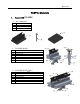
Materials PART A: Materials 1. Items with RT-APEX ① RT-APEX Base 1A 1B 1C Item Base Bracket Screw 5.
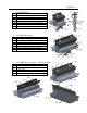
Materials 4A ④ RT-APEX End 4A 4B 4C 4D 4E 4F 4G Item End Clamp U-D Bracket Pillar Bracket Hexagon socket set screw M16×55 Hexagon socket head cap screw M10x50 Hexagon socket head cap screw M8x9 U-D Bonding Clip 4E 4G 4B 4F 4D ⑤ RT-APEX End Splice 5A 5B 5C 5D 5E 5F 5G 4C 5E 5A Item End Splice U-D Splice Pillar Bracket Hexagon socket set screw M16×55 Hexagon socket head cap screw M10x50 Hexagon socket head cap screw M8x9 U-D Bonding Clip 5E 5G 5B 5D 5G 5F ⑥ RT-APEX Floating Splice 6D (Middle
Materials ⑦ RT-APEX Skirt 80 7A Item Eaves Cover L-2032 7A ⑧ RT-APEX Skirt Bonding Splice (Optional) 8A Item Eaves Cover Joint 8A ⑨ RT-APEX Skirt End Cap (Optional) 9A 9B 9C Item End Cap (Left) End Cap (Right) Tapping Screw M4x16 9A 9B 9C 8
Materials ⑩ RT-APEX Screw (Optional) 10A Item Screw M4x16 SDST 10A ⑪ RT-APEX SUMO Clip (Optional) 11A Item SUMO Clip 11A ⑫ RT-APEX Wood Screw (Optional) 12A Item Screw 5.0×90 ! Attentio The 5.0×90mmn stainless wood screw is to 12A be used only on rafters. It has no structural connection installed on the roof sheathing.
Materials 2. Module Clamp Table Clamp Panel Frame Height Middle Clamp 30 – 40 mm RT3-02-UM-30-** RT-APEX Middle Middle Splice 30 – 40 mm RT3-02-UMS-30-** RT-APEX Middle Splice Middle F-Splice 30 – 40 mm RT3-02-UMFS-30-** RT-APEX Middle F-Splice End Clamp 30 – 40 mm RT3-01-UE-30-** RT-APEX End End Splice 30 – 40 mm RT3-01-UES-30-** RT-APEX End Splice End F-Splice 30 – 40 mm RT3-01-UEFS-30-** RT-APEX End F-Splice 3.
LANDSCAPE BRACKET LAYOUT PART B: Landscape Layout 1. Installation of Brackets (1) Brackets Layout a) Installation on the RAFTER Example (Scale: Not to Scale) Note: Minimum distance 1/8” (3 mm) between panels.
LANDSCAPE BRACKET LAYOUT ① Chalk line according to the layout plans to indicate bracket’s position. Y Y Y0 (i) Line Y0: Position the lower base upper edge at 3/16” (5 mm) from the edge of the upper composite shingle. (see illustration bellow) (ii) Line Y1: Delineates the location of the Pillar Bracket’s eaves side for the first row at 4-1/8” (105mm) from Line Y0 (upper edge of base bracket). Y1 T Y T T Y T T Y1 (iii) Line Y: Center of brackets of the second and subsequent rows.
LANDSCAPE BRACKET LAYOUT ② Aligning the brackets. Choose the most suitable rafter for the array, then draw chalk lines to mark their center. Y Y Y0 Y1 (i) Line R: Rafter center line. T The Engineer of Record (EOR) T shall verify the framing capacity T R and fastener installation for T R R building code compliance R including those of the National Design R R Specification for Wood Construction R R (NDS 2005/2012/2015) as applicable.
LANDSCAPE BRACKET LAYOUT b) Installation on the DECK Example (Scale: Not to Scale) Note: Minimum distance 1/8” (3 mm) between panels.
LANDSCAPE BRACKET LAYOUT ① Chalk line according to the layout plans to indicate brackets position. Y Y Y0 (i) Line Y0: (ii) Line Y1: (iii) Line Y: (iv) Line T: Position the lower base upper edge at 3/16” (5mm) from the edge of the upper composite shingle. (see illustration bellow) Delineates the location of the Pillar Bracket’s eaves side for the first row at 4-1/8” (105mm) from Line Y0 (upper edge of base bracket). Y1 T Y T T Y T T Y1 Center of brackets of the second and subsequent rows.
LANDSCAPE BRACKET LAYOUT ② Position the brackets. Select the clamping location (M) according to the PV module installation instructions. (i) Line M: Bracket center line.
LANDSCAPE BRACKET INSTALLATION (2) Bracket Installation ! Attention To maintain the flashing performance, avoid installation when the temperature is below 22F or above 176F. RT Butyl must be installed on a dry and free from debris surface. ① Mark the location at the intersection of the Y0 or Y Line and R/M Line. (Top of the first row bracket.
LANDSCAPE BRACKET INSTALLATION ② Choose “A” or “B” installation at each bracket location. ! Attention Minimum clearance between mounting screws and the edge of the roofing shingle shall be 3/8” (10 mm). In case the stainless screw hit the nail underneath the shingle; 1) Tip the driver at an angle. 2) Use a 3 mm steel drill to make a hole. 3) If possible, remove the nail from underneath.
LANDSCAPE BRACKET INSTALLATION ③ Adjust the RT butyl tape to match the height of the upper shingle. When there is a gap, a slit, or a height difference at the mounting location of the bracket, use additional RT butyl tape (Installation B). ● When there is a slit at the installation spot, fill in with the additional RT butyl tape. The slit must be filled with RT butyl tape. ● When there is a slit above the bracket, fill it in with RT butyl tape to match its shape.
LANDSCAPE BRACKET INSTALLATION ● When there are gaps in the Deck Install position to install, cut RT butyl tape to the shape and apply it. Note: Each bracket comes with a RT butyl tape, and is supplied with an additional tape. ! Attention Peel off the protection paper from the RT butyl tape. Be sure that the RT Butyl tape covers the entire surface of the bracket.
LANDSCAPE BRACKET INSTALLATION Base Leveling Options [Case 1] ● Use RT butyl tape to level the Cut " t eet h" wher e br acket shal l i nst al l surface of the composite shingle roof. When there are gaps in the position to install, cut RT butyl tape to the shape and apply it. It is an option to cut the upper ¡ But yl spacer (unsealed) layer from an architectural shingle once it is unsealed (loose).
LANDSCAPE BRACKET INSTALLATION [Case 2] ¡ But yl spacer ● Building layers of RT butyl for the bracket to be mounted over the teeth region of composite shingle roofs. We recommend 4 layers maximum. Layer 1 is already applied to the bottom of the bracket. ¡ But yl spacer The following layers must be cut to shape to cover the surface of the bracket at each location, assuring a leveled surface.
LANDSCAPE BRACKET INSTALLATION ④ Starting eave edge installation. Brackets shall be installed per installation A (Pg.18). ⑤ Be sure to inspect RT Butyl tape covers the entire surface. If not, use a new mount. ! Attention Do not leave any protective paper on the surface of the RT butyl tape, it can cause an improper seal and may allow water intrusion under the bracket.
LANDSCAPE BRACKET INSTALLATION ⑥ Installing the bracket. Place the brackets at the specified position with RT butyl tape and make sure the RT butyl attaches well to the roofing surface. Set the bracket with 2 ea. screws (for RAFTER), or 5 ea. (for Roof DECK), 5.0×60 mm stainless wood screw using 8 mm socket. After completing process, make sure the brackets are securely fixed. ! Attention ・Note: "R" logo on top right of the base should always be on the ridge side when installing.
LANDSCAPE BRACKET INSTALLATION Deck Install The screw location for Deck Installation ! Attention Note: Proper torque values for the 5.0×60 mm screw will vary depending on the rafter and/or deck characteristics; hardness, age, and moisture of the wood. Tightend until the washer just stop rotating easily.
LANDSCAPE BRACKET INSTALLATION ⑦ [OPTIONAL Sealant Layer] Cover the exposed RT butyl tape with roof sealant. Apply roof sealant around the brackets, the top and each side edge of the brackets. The purpose for the sealant is to add a layer for UV protection. It is not necessary to seal the bottom of the brackets. ※Optional installation on the Ridge (top row) of the array only! (See Pg. 33) This option allows for the end clamp to be installed on the ridge side without removing the top/ridge side clamp only.
LANDSCAPE PANEL INSTALLATION 2. Installation of Panels (1) Aligning and Leveling the Brackets ① Slide in the end & middle clamps to the RT-APEX base. Note : Once the eaves clamp is installed add the ridge clamp so module can be dropped in place. ! Attentio n Be aware of the sharp tip of bonding pin at underside of the clamp flange.
LANDSCAPE PANEL INSTALLATION ② Stretch a string line tight along the Y1 line between the first and last brackets in the first row. ③ Align all the Pillars on the row, using the string line as a guide. Align the Pillars on the eaves side ④ Tighten Head cap M8x9, on bottom side of Pillar to 106 inlbs (12 N・m) torque. ! Attention Maximum Torque value for the head cap M8x9 is 106 in-lbs (12 N・m).
LANDSCAPE PANEL INSTALLATION ⑤ Adjust the height of all the brackets using a hex bit socket (8 mm). Level the bracket height ⑥ Adjusting height shall be done within the range from bottom where the Pillar hits the clamp, to the top where the pillar is flush to the top of U-D bracket. Adjustable height is up to 1” (30mm frame), 1 3/8” (40mm frame).
LANDSCAPE PANEL INSTALLATION If you are installing the Eaves Cover (Skirt) for RT-APEX, Skip to "3. Eaves Cover : Skirt (Optional)” on page 36. (2) End Clamp and the First Row Panel Installation ① Place the PV panel on the U-D bracket. ② Make any adjustment then tighten the end clamp head cap screw M10 to 142 inlbs (16 N ・ m) or 159 in-lbs (18N・m) torque (see UL 2703 appendix for the proper torque value). ③ Repeat ① and ② for all the first row panels.
LANDSCAPE PANEL INSTALLATION (3) Middle Clamp Installation ① Slide the RT-APEX Middle clamp until it is flush to the frame of the panel already installed. ② Tighten the head cap screw M8x9, on the bottom side of the pillar, from side to 106 in-lbs (12 N・m) torque. ③ Tighten the Middle clamp head cap screw M10 to 142 inlbs (16 N ・ m) or 159 in-lbs (18N・m) torque. (see appendix for the proper torque value).
LANDSCAPE PANEL INSTALLATION ④ If necessary, level the height of the brackets using a hex bit socket (8 mm). Adjusting height shall be done within the range from bottom where the Pillar hits the clamp, to the top where the pillar is flush to the top of U-D bracket. Adjustable height is up to 1” (30mm frame), 1 3/8” (40mm frame). Max height line ⑤ Slide in the PV panel from the ridge side. Make sure PV panel frame slides on the inside of the middle clamp.
LANDSCAPE PANEL INSTALLATION (4) Upper End Clamp (Ridge side) Installation Note: If the ridge side (top) base Bracket was rotated 180 degrees as shown on Page 26, skip to ②’ and ③’. ① Untighten the end clamp cap screw M10, and rotate the end clamp only. Set the screw on the same side. ② Slide the RT-APEX end clamp until it is flush with the frame. ③ Tighten the head cap screw M8x9, on the bottom side of the pillar to 106 in-lbs (12 N・m) torque.
LANDSCAPE PANEL INSTALLATION ②’ Slide the RT-APEX end clamp until it is flush with the frame. ③’ Tighten the head cap screw M8x9, on the bottom side of the pillar to 106 in-lbs (12 N・m) torque.
LANDSCAPE PANEL INSTALLATION ④ Tighten the head cap screw M10 to 142 in-lbs (16 N ・ m) torque or 159 in-lbs (18N・m) torque (see appendix for the proper torque value). ⑤ If necessary, level the height of the brackets using Hex wrench bit socket (8 mm). Adjusting height shall be done within the range from bottom where the Pillar hits the clamp, to the top where the pillar is flush to the top of U-D bracket. Adjustable height is up to 1” (30mm frame), 1 3/8” (40mm frame).
Eaves Cover Installation 3. Eaves Cover: Skirt (Optional) ! Attention Skirt is not recommended in areas where the ground snow exceeds 40 PSF. The Skirt when installed across 2 adjacent rows of PV modules will create a bonding path that can replace bonding lugs. (Details on Part E) (1) Install the first row ① After alignment of the first row, put in Eaves cover to U-D Bracket. Note: Eaves cover; Skirt must fit in the channel where Bonding clip is installed at U-D bracket as it shown on picture.
Eaves Cover Installation ② Set the Panel in place and adjust its position, then tighten the Head cap screw M10 to 142 in-lbs (16 N・m) or 159 in-lbs (18N・m) torque (see appendix for the proper torque value). ③ Open 1/8 inch (3mm) between Eave covers next to each other. Back to “(3) Middle Clamp Installation” on Page 31.
Eaves Cover Installation 4. Skirt Bonding Splice: Eaves Cover Joint (Optional) ① Slide in Skirt Bonding Splice to the edge of Eaves Cover. Skirt Bonding Splice has a tooth which shall be face down to bottom. Please slide in the Skirt Bonding Splice until the teeth scratches the side wall. You may use rubber mallet to install it. ! Attentio n Make sure the teeth facing down to bottom of Skirt. ② There is a 3mm gap between each Skirt, and the teeth create this 3mm gap once installed correctly.
Eaves Cover Installation 5. Skirt End Cap (Optional) ① Place and secure the Skirt End Cap to the side of Eaves Cover. ! Attentio End Cap kit include Left and Right n Cap. Please make sure to install correct side to each end of Skirt. ② Use Tapping Screw M4 x 16 to secure the End Cap. ③ Please install on both sides.
Side Screw Installation 6. Side Screw (Optional) ① The optional side screw M4 x16 SDST increases the load capacity specially in heavy snow locations. It allows for an increased span. Consult the PE stamped letters for the span values marked with *. Use Hex socket drive (7 mm) to set the screw M4×16 SDST as showed in picture below.
SUMO clip Installation 7. SUMO Clip (Optional Canada and Florida HVHZ) Only OSB Deck Installation ! Attentio OSB attachmentnwith SUMO clip requires 6ea 5×60mm wood screws. ① Once the Pillar is set in place with the M8x9 screw, the SUMO clip can slide all the way in. ② Use M4x16 SDST screw to fix the SUMO Clip and Pillar Bracket together on both sides. First set the side overlapping the Pillar Bracket since the M4x16 SDST screw will have to match the hole on the Pillar Bracket.
Splice Installation PART C: Splice Installation ! Attention Both supported splice and floating splice must be an approved method and included in the PV module manufacturer installation instructions. 1. Installation of Splice Brackets (1) Brackets Layout (Including Splice) a) Installation on the RAFTER Example (Scale: Not to Scale) Note: Minimum distance 1/8” (3 mm) between panels.
Splice Installation b) Installation on the DECK ① Example (Scale: Not to Scale) 43
Splice Installation b) Installation on the DECK ② (Floating Splice) Example (Scale: Not to Scale) Note: It is an option to install a Floating Splice (no roof connection) based on the PV module installation instructions and the structural analysis (PE Stamped letters provided). Please refer to Page 7 for Floating Splice installation.
Splice Installation c) Splice Installation Area ① If the Splice is installed at the corner of the module, the module frame must sit at least 1-3/16” (30mm) away from the edge of the clamp. PV panel corner on the left side PV panel corner on the right side Note : When designing for the splice, notice its center is offset by 7/8” (22mm) from the R/M line, when the Base Bracket is installed at the center of the R/M line.
Splice Installation ② Switching the sides of the pillar will allow a 45mm lateral adjustment. The edge of the PV module can be mounted within 3” from the R/M lines (as shown).
Splice Installation (2)-1 Floating Splice Installation on the First Row (eaves side) ※ Install the End splice for the first and the ridge rows installation. (First Row ; A base is needed on the eaves side) ① End Floating Splice shall be installed with Base Bracket for the first Row. (Also shown on Pgs. 49 & 53) ※ In case of the floating splice with the skirt between two mounts.
Splice Installation ② (2)-2 The Ridge (top row) Floating Splice doesn’t need a base and shall be installed by rotating the clamp 180 degrees (The flat section of the UD bracket in full contact with PV module frame) Middle Floating Splice Installation ① After first row is installed, Middle Floating Splice can be installed all the way to the ridge with no need of a base. (Detail is shown from Pgs.
Splice Installation (3) End Splice and the First Row Panel Installation ① Place the PV panel on the U-D Splice. ② Make any adjustment then tighten the Head cap screw M10 to 142 in-lbs (16 N・m) or 159 in-lbs (18N・m) torque (see appendix for the proper torque value). ③ Repeat ① and ② for all the first row panels.
Splice Installation (4) Middle Splice Installation ① Slide the RT-APEX Middle Splice until it is flush to the frame of the panel already installed. ② Tighten Head cap screw M8x9, on bottom side of Pillar, from side with 106 in-lbs (12 N・m) torque. ! Attention Maximum Torque value for the head cap M8x9 is 106 in-lbs (12 N・m).
Splice Installation ③ Tighten the Head cap screw M10 to 142 in-lbs (16 N・m) or 159 in-lbs (18N・m) torque (see appendix for the proper torque value). ④ If necessary, level the height of the brackets using Hex wrench bit socket (8 mm). Adjusting height shall be done within the range from bottom where the Pillar hits the clamp, to the top where the pillar is flush to the top of U-D bracket. Adjustable height is up to 1” (30mm frame), 1 3/8” (40mm frame).
Splice Installation ⑤ Slide in PV panel from ridge side. Make sure PV panel frame fits to the inside of the Middle clamp.
Splice Installation (5) Upper (Ridge side) End Splice Installation Note: If the ridge side (top) base Bracket was rotated 180 degrees as shown on Page 26, skip to ②’ and ③’. ① Untighten End Splice Clamp Head cap screw M10, and rotate the clamp 180 degrees. ② Slide the RT-APEX End Splice until it is flush to the frame of the panel already installed. ③ Tighten the head cap screw M8x9, on the bottom side of the Pillar, to 106 in-lbs (12 N・m) torque.
Splice Installation ② ’ Slide the RT-APEX End Splice until it is flush to the frame of the panel already installed. ③’ Tighten the head cap screw M8x9, on the bottom side of the Pillar, to 106 inlbs (12 N・m) torque.
Splice Installation ④ Tighten the Head cap screw M10 to 142 in-lbs (16 N・m) or 159 in-lbs (18N・m) torque (see appendix for the proper torque value). ⑤ If necessary, level the height of the brackets using Hex wrench bit socket (8 mm). Adjusting height shall be done within the range from bottom where the Pillar hits the clamp, to the top where the pillar is flush to the top of U-D bracket. Adjustable height is up to 1” (30mm frame), 1 3/8” (40mm frame).
PORTRAIT BRACKET LAYOUT PART D: Portrait Layout 1. Installation of Brackets (1) Brackets Layout a) Installation on the RAFTER Example (Scale: Not to Scale) Note: Minimum distance 1/8” (3 mm) between panels.
PORTRAIT BRACKET LAYOUT Note: The Base direction to install PV panel in Portrait is same direction as PV panel in Landscape. ! Attention Supported splice must be an approved method and included in the PV module manufacturer installation instructions.
PORTRAIT BRACKET LAYOUT b) Installation on the DECK ① Example (Scale: Not to Scale) Note: Minimum distance 1/8” (3 mm) between panels.
PORTRAIT BRACKET LAYOUT b) Installation on the DECK ② (Floating Splice) Example (Scale: Not to Scale) Note: Minimum distance 1/8” (3 mm) between panels. ! Attention A floating splice must be an approved method and included in the PV module manufacturer installation instructions.
PORTRAIT BRACKET LAYOUT b) Installation on the DECK ③ Example (Scale: Not to Scale) Note: Minimum distance 1/8” (3 mm) between panels.
Electrical Setup PART E: Electrical Setup 1. Cable Management Cable Management of the U-D Bracket (U-D Splice) ① Cables and wires can be routed inside the tray under U-D Bracket. ② If Cables and wires are loose, use a cable tie through the U-D bracket hole. Note : Cable Tray can hold 2 to 3 cables depending on the gauge and insulation.
Electrical Setup 2. Grounding Setup All electrical installation and procedures should be conducted by skilled, licensed and bonded electricians. Installer is responsible for and shall provide an appropriate method of direct-to-earth grounding in accordance with the latest edition of the Canadian Electrical Code Part 1, CSA 22.1 Safety Standard for Electrical Installations or the National Building Code, including NEC 250: Grounding and Bonding, and NEC 690: Solar Photovoltaic Systems.
Electrical Setup Example ② Example ③ 63
Electrical Setup 3. Bonding Path Diagrams A: Bonding Middle Clamp ① The stainless steel bonding teeth integrated in the Middle Clamp pierces the module frame anodization to bond module to module through the clamp. (Bonding path between PV panels) ② The toothed washer bonds the aluminum Middle Clamp to the stainless steel head cap screw, removing the clamp anodization. ③ The head cap screw thread creates the A bonding path to the U-D Bracket.
Electrical Setup C: Bonding Splice (Middle and End) ① The stainless steel bonding teeth integrated in the splice clamp pierces the module frame anodization to bond module to module through the clamp. (Bonding path between PV panels installed next to each other) C C’: Bonding Floating Splice (Middle and End) ① The stainless steel bonding teeth integrated in the splice clamp pierces the module frame anodization to bond module to module through the clamp.
Electrical Setup D: DynoBond ① DynoBond 8” Can be an option for PV frames not listed. Limited to a 20A Maximum Fuse Rating.
Electrical Setup E: Bonding Eaves Cover ① The stainless steel bonding teeth integrated in the end clamp pierces module frame anodization to bond module to clamp. ② The toothed washer bonds the aluminum end clamp to the stainless steel head cap screw, removing the clamp anodization. ③ The head cap screw thread creates the bonding path to the U-D Bracket. ④ The U-D bonding clip of the U-D E Bracket holds the eaves cover in to the channel, and its teeth and surface creates a bonding path.
Electrical Setup F: WEEB Lug or ILSCO Lug ① WEEB washer dimples or ILSCO Lug teeth pierces the anodized module frame to bond the frame to the lug. ② Solid copper wire connected to the lug is routed to provide final system ground connection. F G: ILSCO Lug attached to the U-D Bracket ① The ILSCO Lug teeth creates a bonding path between U-D Bracket and grounding wire. ② Solid copper wire connected to the lug is routed to provide the final system ground connection.
Electrical Setup Example of Bonding Path ① In order to properly ground the PV modules and the brackets to the equipment ground, a grounding lug or lay-in lug must be attached to the PV module or the RT-APEX’s U-D Bracket at the end of each row. When the skirt is bonding the adjacent rows, there is no need to attach the grounding lug at the end of each row (see examples 2 and 3) Notice that the PV frame is part of the bonding path. Note: Grounding, Bonding lugs and Straps are not provided by Roof Tech Inc.
Electrical Setup Example of Bonding Path ② (Bonding path through Skirt and Skirt Splice) Example of Bonding Path ③ (Bonding path through Skirt) 70
Electrical Setup Example of Bonding Path ④ (Bonding path through Splice Bracket) Example of Bonding Path ⑤ (Bonding path through Floating Splice Bracket) 71
ADDENDUM Installation Instruction for metal roofing Installation on a Metal Roofing 1. Requirement ・ The Roof Tech P.E. Letters are created for a minimum 7/16” OSB with 2x4” rafters 24 in o.c. IMPORTANT: Metal roofs have a high thermal expansion and contraction factor. Screwing through a standing seam metal roof is not recommended and will also void the roof warranty. Exposed fastener metal roofs have a lesser impact from thermal expansion, however attention to the panel length is important.
ADDENDUM Installation Instruction for metal roofing 2. Marking on the Roof (1) Layout ① The Base bracket must be mounted on the flat surface. Please make sure the location is not on slope surface of metal ribs. Screw must be fixed to the flat surface. Also, its center must clear 5mm from the edges (Please refer to the 3 pictures on the right.) ② Make at +45mm from the [Fastening to the Deck] intersection of the M line and Y line on the M line. ③ Make at ±28mm from the M line.
ADDENDUM Installation Instruction for metal roofing (2) Check the height of metal rib. 5mm Maximum height H ① Use Center punch to make a pilot hole. You can mark on roof or use base’s screw hole directly from top of the base. Must be no gap underneath for the use of a center punch.
ADDENDUM Installation Instruction for metal roofing 3. Bracket Installation ① Please add a butyl pad (RT Butyl Spacer) on the surface between the ridges. ② Peel off the protective paper from the RT butyl tape. ! Attention Do not leave any protective paper on the surface of the RT butyl tape, it can cause an improper seal and may allow water intrusion under the bracket. ③ Place the brackets at the specified location and make sure the RT butyl attaches well to the roofing surface.
ADDENDUM Installation Instruction for metal roofing ④ Set the bracket with 5 ea. (for Roof DECK), of M5.0×60 mm stainless wood screw using 8 mm hex socket. After completing process, make sure the brackets are securely fixed. ! Attention When the base is installed on the deck, 5 screws must be used. The screws are fixed into the side 4 holes and 1 ridge side hole. Note; Each base is shipped with 2 mounting screws. The installer must purchase additional screws when mounting it to the roof deck.
ADDENDUM Installation Instruction for metal roofing ⑤ Apply roof sealant on the ridge side of the brackets to from a slope and triangle. Optional is the sealant to each side of brackets. Do not apply sealant to the bottom of the brackets.
ADDENDUM Installation instructions on composite slate Installation on a Composite Slate 1. Requirement ・ Composite Slate, compatible with RT Butyl 2. Marking on the Roof (1) Layout ① Make at +45mm from the intersection of the M line and Y line on the M line. ② Make at ±28mm from the M line. ③ Then make at ±25mm, ±35mm from the Y line. (See illustrations.
ADDENDUM Installation instructions on composite slate 3. Bracket Installation ① Drill a pilot hole to fill with sealant with a φ1/4 inch (φ6.5 mm) drill bit at the markings. Note:It is easier to manage drill depth by using any stopper on the drill bit. Please make sure to use stopper to drill through the layer of roofing material only. Do not to drill all the way to the wood deck or underlayment. ! Attention You must avoid drilling into the wood underneath it.
ADDENDUM Installation instructions on composite slate ③ Set the bracket with 5 ea. (for Roof DECK), of M5.0× 60 mm stainless wood screw using 8 mm hex socket. ! Attention When the base is installed on the deck, 5 screws must be used. The screws are fixed into the side 4 holes and 1 ridge side hole. Note; Each base is shipped with 2 mounting screws. The installer must purchase additional screws when mounting it to the roof deck.
APPENDIX List of PV Modules compatible with this racking system. The Roof Tech RT-APEX rail-less PV mounting system is certified to UL 2703 and may be used to ground and/or mount a PV module complying with UL 1703 only when the specific module has been evaluated for grounding and/or mounting in compliance with the included instructions. Unless otherwise noted, “xxx” refers to the module power rating and both black and silver frames are included in the certification.
APPENDIX Manufacturer Meyer Burger Peimar REC Silfab Solaria PV module Model No.
APPENDIX Manufacturer VSUN Yingli PV module Model No.
APPENDIX ※Torque value of 18Nm: Manufacturer Astronova PV module Model No. CHSM6612P, CHSM6612P/HV CHSM6612M-HV-xxx, CHSM6612P-HV-xxx, Astroenergy CHSM72M(DG)/F-BH, CHSM72M-HC xxxW, CHSM72M(DG)/F-BH xxxW BYD Certainteed P6K Series (35mm), MHK-36 CTxxxMxx-01, CTxxxPxx-01, CTxxxMxx-02 Where “xx” denotes frame and backsheet color. CT-03 Series CTxxxHC11-04 Dehui Solar Eco Solargy DH-60M xxx-xxxW ORION 1000 ECOXXXH156P-60, APOLLO 1000 ECOXXXT156M-60, and APOLLO 1000 ECOXXXA156M- 60.
APPENDIX ※Torque value of 18Nm: Manufacturer PV module Model No.
APPENDIX Manufacturer S-Energy PV module Model No.
NOTES 87
Customer Support If you need assistance at any point of your installation or have suggestions on how can we improve your experience, call Roof-Tech customer support. (858) 935-6064 http://roof-tech.