Dec./2021 INSTALLATION MANUAL RT-MINI Ⅱ 10620 Treena St, Suite 230 San Diego, California 92131 TEL (858) 935-6064 www.roof-tech.
INSTALLATION MANUAL Contents ・Introduction -----------------------------------------------------------1 ・Periodical Inspection ------------------------------------------------2 ・Tools Required for Assembly -------------------------------------3 ・Technical Note -----------------------------------------------------3 ・Moisture Content ----------------------------------------------------4 ・Installation Safety ---------------------------------------------------4 PART A: Materials -------------------------------
Introduction Introduction Please review this manual thoroughly before installing your Roof-Tech system. Aside from reading this manual, please review the P.E. Stamped Engineering Letters for the RT-MINI Ⅱ products for your State. The Roof Tech Structural Stamped letters are prepared based on 2 layers of shingles.
Introduction ・Roof Tech recommends a thermal splice ( a gap between rails) every 14 Ft., however, it must be determined by the installer based on the rail system installation instructions. The installer must also determine the maximum allowed span and cantilever design parameters recommended by the rail system manufacturer. The RT-MINI Ⅱ can be installed on low slope roofs (Metal, EPDM, TPO, SBS Modified Bitumen/Torch-on, Asphalt) and steep slope roofs (Asphalt shingles, Metal).
Tools Required for Assembly Technical Note Tools Required for Assembly Tools needed for installing the RT-MINI Ⅱ ・Hex bit socket (8mm) ・Drill andφ3 mm Drill Bit or Center punch for sheet metal (for Installation on Metal Roof) ・Measuring tape ・Chalk line ・Torque Wrench ※L-Foot mounting option Item RT2-04-FBN 25 SL-5/16 Flanged Bolt and Flanged Nut Torque 15.
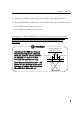
Moisture Content Safety Moisture Content RT Butyl Flexible Flashing is to be installed on dry mounting surfaces. Determining how wet is too wet: First, remove the paper backing from an RT product exposing the clean RT Butyl. Second, press the base, RT Butyl side down against the surface. Third, pick up the base. If the base adheres to the roof, the roof is suitably dry for installation.
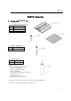
Materials PART A: Materials 1. Items with RT-MINI Ⅱ ① RT-MINI Ⅱ Bracket Set 1A 1B 1C Item RT-MINI Ⅱ Screw 5.0×60 RT Butyl Flashing ② Screw(Optional) 2A Item Screw 5.0×90 ③ Roof sealant 3A Item Roof sealant ※Recommended Product ・Henry : 208R, 209, 925 (Black) ・Geocel:S2, S4 (Black) ・Sashco : Through the Roof ・Boss : 125 (Black) ・Top Industrial: Rain Buster 850, 900 ・Chem Link: M1 ・NPC Solar Seal 900 ・GE All Purpose 100% Silicone The Sealant adds a layer of UV protection to the Flexible Flashing.
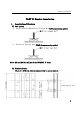
Bracket Installation PART B: Bracket Installation 1. Installation of Brackets (1) Bolt options a) For the RT2-04-FBN25SL 5/16” Flanged Bolt (L-Foot mounting option) b) For the 1/4” Carriage Bolt. (EMT clamp mounting option) Note: M8 and M6 Bolt will not fit the RT-MINI Ⅱ base. (2) Brackets Layout There is 1 9/16 inch (40mm) adjustability to secure the bolt.
Bracket Installation ① Locate and place MINI Ⅱ base on the cross section of chalk line. ② Protecting the edge of the shingles. Note: The MINI Ⅱ base is structurally engineered to be mounted in the above position (structural). However if used for accessories such as junction boxes or EMT with no structural value, It can then be mounted on any orientation.
Bracket Installation ③ Chalk line according to the layout plans to indicate bracket’s position. ④ Aligning the brackets. Choose the most suitable rafter, then mark the center. (ⅰ) Line M: Vertical Bracket center line. (ⅱ) Line Y: Horizontal Bracket center line. The Engineer of Record (EOR) shall verify the framing capacity and fastener installation for building code compliance including those of the National Design Specification for Wood Construction (NDS 2005/2012/2015) as applicable.
Bracket Installation (3) RT-MINI Ⅱ Mounting Options ① Rafter installation (Center) : Fastened in the center to the Rafter with 2ea. M5.0×60 mm or M5.0×90 mm wood screws. ② Rafter installation (Offset) : Fastened to the Rafter offset with 2ea. M5.0 ×60 mm wood screws on either side and 3ea. M5.0×60 mm wood screws to the sheathing.
Bracket Installation ③ Deck installation : Fastened to the sheathing (Plywood or OSB) with 5ea. M5.0×60 mm wood screws. Note: Verify the PE stamped letters for maximum span values.
Bracket Installation (4) Bracket Installation ! Attention To maintain the flashing performance, avoid installation when the temperature is below 22F or above 176F. RT Butyl must be installed on a dry surface. ① Mark the location at the intersection of the Y Line and M Line. ! Attention Minimum clearance between mounting screws and the edge of the roofing shingle shall be 3/8 inch (10 mm). In case the stainless screw hit the nail underneath the shingle; 1) Tip the driver at an angle.
Bracket Installation ② Adjust the RT butyl tape to match the height of the upper shingle. When there is a gap, a slit, or a height difference at the mounting location of the bracket, use additional RT butyl tape. ● When there is a slit at the installation spot, fill in with the additional RT butyl tape. The slit must be filled with RT butyl tape. ● When there is a slit above the bracket, fill it in with RT butyl tape to match its shape. Apply roof sealant around the RT butyl tape.
Bracket Installation Rafter Install ③ If there is a shingle gap within 2 inches from the base, sealant shall be applied to the gap as it is shown. ● Best to position bracket 2 inches from the slit. the away ● If the mounting screw is within less than 2 inches from the slit, fill the slit with roof sealant.
Bracket Installation Leveling the Base Options [Case 1] ● Use RT butyl tape to level the surface of shingle roof. the Cut "teeth" where bracket shall install composite ■Butyl spacer ■Butyl spacerr ■Butyl spacer ■Butyl spacer Flush with shingle . Note:Do not splice the butyl tape.
Bracket Installation [Case 2] ■Butyl spacer ● Building layers of RT butyl for the bracket to be mounted over the teeth region of composite shingle roofs. We recommend 4 layers maximum. Layer 1 is already applied to the bottom of the bracket. ■Butyl spacer The following layers must be cut to shape to cover the surface of the bracket at each location, assuring a leveled surface.
Bracket Installation [Case 3] ● Roofing Leveling Option The application of one layer of asphalt roofing shim with the proper asphalt roofing cement is an alternative to leveling when a Roof Tech base is to be installed between 2 levels (layers of asphalt shingles). ④ Peel off the protective paper from the RT butyl tape. ! Attention Do not leave any protective paper on the surface of the RT butyl tape, it can cause an improper seal and may allow water intrusion under the bracket.
Bracket Installation ⑤ Installing the bracket. [Fastening it to the Rafter] Place the brackets at the specified position and make sure the RT butyl makes good contact with the roofing surface. Slide the 5/16” Flanged bolt into place before fastening the bracket on the roof. Set the bracket with 2 ea. Screws, M5.0 × 60 mm stainless wood screw using 8mm hex socket. After completing process, make sure the brackets are securely fixed.
Bracket Installation [Fastening it to the Roof Deck] ! Attention When the MINI Ⅱ base is installed on the deck, 5 screws must be used. Four screws are fixed into the sides and 1 on the ridge side. Note; Each MINI Ⅱ is shipped with 2 mounting screws. The installer must purchase additional screws when mounting it to the roof deck. ! Attention Note: Proper torque values for the 5.0×60 mm screw will vary depending on the rafter and/or deck characteristics; hardness, age, and moisture of the wood.
Bracket Installation ⑥[OPTIONAL Sealant Layer] Apply roof sealant to the top and each side edge of the brackets. This adds additional UV protection. Cover the exposed RT butyl tape with roof sealant. No need to apply it to the bottom of the brackets. ! Attention You may verify that the screws underneath the deck panel are stained with butyl rubber. This indicates a good flashing performance. the deck panel are stained with butyl rubber.
Conduit Strap Installation 2. Conduit Strap Installation (Optional) (1) A conduit Strap can be installed on top of MINI II ① Align the conduit Strap to the groove on top of MINI II ② Use the SDST screw to fix the conduit Strap. Length of SDST screw must not exceed 5/8”. ! Attention The SDST SCREW length must not exceed 5/8”.
ADDENDUM Installation Instruction for metal roofing Installation on a Metal Roofing 1. Requirement ・ The Roof Tech P.E. Letters are created for a minimum 7/16” OSB with 2x4” rafters 24 in o.c. IMPORTANT: Metal roofs have a high thermal expansion and contraction factor. Screwing through a standing seam metal roof is not recommended and will also void the roof warranty. Exposed fastener metal roofs have a lesser impact from thermal expansion, however attention to the panel length is important.
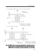
ADDENDUM Installation Instruction for metal roofing 2. Marking on the Roof (1) Layout ① The MINI Ⅱ base must be mounted on the flat surface. Please make sure the location is not on slope surface of metal ribs. Screw must be fixed to the flat surface. Also, its center must clear 5mm from the edges (Please refer to the 3 pictures on the right.) ② In case of Deck Installation, mark at ± 15 mm, ± 25 mm from the intersection of [Fastening to the Deck] the M Line and Y Line. ③ Then mark at ±32.
ADDENDUM Installation Instruction for metal roofing (2) Check the height of metal rib. 1)The maximum height “H” is 5mm. ① Use Center punch to make a pilot hole. You can mark on roof or use base’s screw hole directly from top of the base.
ADDENDUM Installation Instruction for metal roofing 3. Bracket Installation ① Please add a butyl pad (RT - Butyl Spacer) on the surface between the ridges. ② Peel off the protective paper from the RT butyl tape. ! Attention Do not leave any protective paper on the surface of the RT butyl tape, it can cause an improper seal and may allow water intrusion under the bracket. ③ Place the brackets at the specified location and make sure the RT butyl attaches well to the roofing surface.
ADDENDUM Installation Instruction for metal roofing ④ Set the bracket with 5 ea. (for Roof DECK), of M5.0 × 60 mm stainless wood screw using 8 mm hex socket. After completing process, make sure the brackets are securely fixed. ! Attention When the MINI Ⅱ base is installed on the deck, 5 screws must be used. The screws are fixed into the side 4 holes and 1 ridge side hole. Note; Each MINI Ⅱ is shipped with 2 mounting screws. The installer must purchase additional screws when mounting it to the roof deck.
ADDENDUM Installation Instruction for metal roofing ④ Apply roof sealant on the ridge side of the brackets to form a slope and triangle. Optional is the sealant to each side of the brackets. Do not apply sealant to the bottom of the brackets.
ADDENDUM Installation Instruction for Composite Slate Installation on a Composite Slate 1. Requirement ・ Composite Slate, compatible with RT Butyl 2. Marking on the Roof (1) Layout ① The MINI Ⅱ base must be mounted on the flat surface. ② Mark at ± 15 mm, ± 25 mm from the intersection of the M Line and Y Line. ③ Then mark at ± 32.5 mm from the M Line ④ Mark at +35 mm from the Y Line on the M Line.
ADDENDUM Installation Instruction for Composite Slate 3. Bracket Installation ① Drill a pilot hole to fill with sealant with a φ1/4 inch (φ6.5 mm) drill bit at the markings. Note:It is easier to manage drill depth by using any stopper on the drill bit. Please make sure to use stopper to drill through the layer of roofing material only. Do not to drill all the way to the wood deck or underlayment. ! Attention You must avoid drilling into the wood underneath it.
ADDENDUM Installation Instruction for Composite Slate ③ Set the bracket with 5 ea. (for Roof DECK), of M5.0× 60 mm stainless wood screw using 8 mm hex socket. ! Attention When the MINI Ⅱ base is installed on the deck, 5 screws must be used. The screws are fixed into the side 4 holes and 1 ridge side hole. Note; Each MINI Ⅱ is shipped with 2 mounting screws. The installer must purchase additional screws when mounting it to the roof deck.
ADDENDUM MINI used with L-Foot and Rail It is important that the designer and installer are acquainted with the PE stamped letters posted on http://www.roof-tech.us/support.
ADDENDUM MINI used with L-Foot and Rail 31
32
Customer Support For assistance call Roof Tech customer support. (858) 935-6064 http://roof-tech.